
Rapid tooling manufacturing based on FDM prototype
With the development of computers, lasers, electronics, new materials, and new technologies, rapid prototyping and rapid molding technology have become even more powerful, with their application scope expanding and their types increasing.
The combination of rapid molding technology and FDM technology has the characteristics of short molding cycle, low cost, accuracy and lifespan that can meet production and use requirements. It can quickly respond to changes in market and user needs and speed up the launch of products on the market. For small and medium-sized molds with relatively complex shapes, it has significant comprehensive economic benefits.
Other Language: DE
What is FDM?
Fused Deposition Modeling (FDM), also known as filament freeform fabrication, is a 3D printing process that utilizes a continuous filament of specialized material. This filament is drawn from a large spool and fed through a heated printer extruder head. The material is then deposited onto the growing workpiece.
The print head, controlled by a computer, moves in two dimensions to define each horizontal layer of the printed object. After completing a layer, either the print head or the workpiece moves vertically by a small amount to begin the next layer. The extruder head’s speed can be adjusted to start and stop the deposition process, allowing for the creation of interrupted planes without causing stringing or dribbling between sections.
Why rapid tooling need FDM technology?
As technology advances and the time it takes for the market to respond to demand shortens, a faster, less expensive production technology is needed. Rapid tooling development benefits from the speed, cost-effectiveness, and flexibility of Fused Deposition Modeling (FDM) technology. FDM can quickly produce mold parts, shorten lead times, and accelerate product development. It allows for easy customization and modification directly in the digital model, which can then be reprinted quickly. FDM is also able to create complex geometries that may be difficult to achieve with traditional manufacturing methods, and it supports a wide range of thermoplastic materials suitable for a variety of applications. As an additive manufacturing process, FDM reduces waste by using only the material required for the part. In addition, tools produced by FDM are ideal for prototyping and testing, helping to identify and resolve potential problems before more expensive and time-consuming production methods are adopted.
Fused deposition modeling (FDM) technology
1.Working principle of FDM process
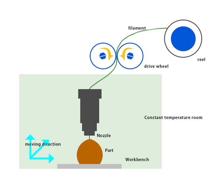
FDM has become one of the most popular rapid prototyping processes. Its working principle is shown in Figure 1: After the three-dimensional solid model is processed by the layering software, the two-dimensional contour information of each layer is obtained. The heating nozzle moves in a plane under the control of the computer according to the information of the cross-sectional contour, and the heated and molten wire (such as plastic wire, nylon, etc.) is selectively coated on the workbench, and the cross-sectional contour is formed after rapid cooling.
After the cross-sectional contour of one layer is completed, the workbench descends a layer height, and then the cross-sectional contour of the next layer is pressed, and the heated and melted wire is coated and bonded to the solidified wire of the previous layer, and the cycle is repeated until the final three-dimensional product is obtained.
According to the forming mechanism of FDM, any fusible material can be used in theory. At present, materials such as wax, nylon, and plastic are often used. People are studying the application of materials such as metals and ceramics to this method. Ceramic or metal powder (stainless steel, brass, aluminum, iron, etc.) is added with polymer adhesives, and the polymer is burned at high temperature after molding to obtain metal parts. In order to improve the molding speed and accuracy of the FDM process, further research is needed in terms of the path generation method, the movement speed of the nozzle in the plane, and the feed speed of the material.
2. Analysis of molding accuracy of FDM process
The accuracy of molded parts includes dimensional accuracy and surface accuracy. The factors affecting the final accuracy of FDM molded parts include not only the accuracy of the molding equipment itself, but also some other factors such as layered slicing error, material shrinkage error, molding process parameter setting, etc. These factors are often more difficult to control. At present, the final dimensional accuracy of the prototype that can be achieved by FDM process is only at the level of ±(0.1~0.2)mm/100mm.
(1) Error caused by molding system
In addition to the verticality of the X and Y axis guide rails of the equipment and the verticality of the Z axis and the worktable, the factors that affect the molding accuracy of the molding system include the motion positioning accuracy and repeat positioning accuracy of the nozzle. The main factor affecting the repeat positioning accuracy of the nozzle is its scanning drive mode. The scanning of the FDM molding head is driven by an AC servo motor through a precision ball screw and guided by a precision linear ball guide. Its position accuracy depends on the accuracy of the encoder in the servo motor (i.e., the number of pulses generated per revolution) and the lead of the ball screw that converts the motor’s rotational motion into linear reciprocating motion[1]. With modern CNC technology and precision transmission technology, the motion positioning accuracy of the nozzle can be controlled within +20um, and the repeatability of the nozzle can be controlled within +10μm[2,3].
(2) Errors caused by layered slicing
Most rapid prototyping systems, including FDM, use the standard STL (Stereo Lithography interface specification) file format of the solid CAD model developed by 3D Systems in the United States in 1989 to define the molded parts. It uses small triangular plane units to discretize and approximate the surface of the three-dimensional solid, and obtains a series of small triangle data information that approximates the original three-dimensional solid. When using triangular facets to approximate the three-dimensional surface of space, it will bring about size, shape and surface errors. Increasing the number of facets can reduce these errors, but they cannot completely eliminate these errors, and will cause the STL file to be bulky and the processing time to increase[4].
The parts molded by the FDM process are made of layers of wires with a certain thickness bonded and stacked one by one.
Like the LOM process, it will inevitably produce a “step” effect, making the surface of the part just a step approximation of the original CAD model surface. The existence of this error significantly reduces the accuracy of the part. In principle, reducing the layer thickness can reduce this error, but reducing the layer thickness will inevitably increase the part molding time and reduce production efficiency. In addition, the specific processing thickness of each layer will be limited by the spinneret diameter. The layer thickness currently used in the FDM process is generally 0.2~0.3mm.
(3) Errors caused by spinning
The cross-sectional profile obtained after layering has a contour line of zero width. In the actual processing process, the molten wire ejected from the nozzle has a certain width. If the ideal contour line of the layered cross section is filled, the final entity will have an extra half of the cross-sectional width of the extruded wire. Although this error can be eliminated by radius compensation in the process control software. However, the cross-sectional width of the extruded wire will change with the changes of factors such as extrusion speed and filling speed during the processing process. Compensation with a fixed radius value will definitely cause errors. In addition, due to speed response problems when the nozzle is switched on and off, the ejected molten wire will accumulate on the prototype to form nodules or vacancies. All of these will cause surface quality problems of the prototype.
(4) Errors caused by material shrinkage
During LOM molding, the ejected wire will shrink when it changes from a molten state to a solid state, making the actual size of the molded part different from the designed size. It is necessary to compensate for the ideal contour line in the process planning stage. The physical properties of the material itself, the shape and size of the parts, the setting of process parameters such as temperature and filling speed during the molding process, and the length of molding time for each layer all affect the shrinkage of the molding material. Therefore, when compensating for the ideal contour line, it is necessary to determine it based on the combined influence of these factors.
(5) The influence of FDM process parameter settings on molding accuracy
During the FDM molding process, the accuracy of the equipment itself, such as the accuracy of the screw guide rail, cannot be adjusted by the user, but some process parameters can be controlled and adjusted by the user. For different equipment, the combination setting of its process parameters needs to be accumulated through experience to find the rules.
Zou Guolin from Dalian University of Technology obtained the relationship between processing parameters and prototype quality through orthogonal experimental design, optimized the process parameters, and formed a complete set of FDM molding process procedures based on parameter optimization settings based on the optimization results[5]. For a given FDM molding system, the optimization setting of process parameters will greatly improve the quality of prototype parts without incurring additional costs.
Rapid tooling manufacturing based on FDM prototype
Fused deposition modeling (FDM process) is a rapid prototyping process that is widely used after laser selective photosensitive resin curing (SLA process). The materials that can be used in the FDM process are very wide, and wax, nylon, plastic, etc. are often used at present; the utilization rate of materials in the FDM molding process is very high, unlike the LOM process, which requires the separation of waste materials and prototypes, so the FDM process has the advantage of low operating costs. If the FDM process, which is widely used in China, can be applied to rapid tooling manufacturing, it will undoubtedly bring great economic benefits. The main purpose of this section is to find a way to use FDM prototypes, refer to the research on the application of LOM prototypes in rapid tooling manufacturing in the previous chapter, and find a way to apply FDM to rapid tooling manufacturing.
1. Application of FDM technology in rapid tooling manufacturing
Like other rapid prototyping technologies, the application of FDM in rapid tooling manufacturing has received widespread attention. FDM technology is usually applied in rapid tooling manufacturing through the following ways:
(1) Precision casting method
The wax, nylon, plastic and other prototypes processed by FDM technology are used as plaster molds, ceramic molds, sand molds and other castings, and then the mold cavity is obtained by investment casting.
(2) Direct manufacturing of metal parts
People are studying adding polymer adhesives to ceramic or metal powders (stainless steel, brass, aluminum, iron, etc.), and then burning off the polymer at high temperature after molding with FDM technology to obtain metal parts. This method can directly manufacture metal mold cavities.
(3) Silicone rubber or resin casting method
Put the FDM prototype into the mold frame and pour liquid silicone rubber or liquid resin mixed with other materials. After it solidifies, it can be separated from the prototype to obtain an injection mold suitable for small batches.
(4) Metal spraying method
Using the FDM prototype as the base mold, spray low-melting-point metal or alloy onto the surface of the mold to form a thin metal shell, and then backfill with composite materials to quickly make a mold.
(5) Electroforming method
After conducting the surface of the FDM prototype, copper can be electroformed to a certain thickness and then backed as an electrode for EDM: Nickel and its alloys can also be directly electroformed on the surface of the FDM prototype and directly used as a mold cavity after backing.
2.Selection of Rapid Prototyping Route
Combined with relative study, the electroplating method with high replication accuracy should be used to manufacture EDM electrodes or mold cavities to avoid thermal shrinkage and complex operating conditions in thermal processing methods. Since the FDM molding process used in the project is to perform spin molding on ABS, the resulting ABS prototype has good chemical plating performance[6], unlike the LOM prototype, which requires sealing treatment or resin re-molding, it can avoid the reduction in dimensional accuracy caused by these processes. Therefore, combining FDM rapid prototyping and electroplating processes can achieve rapid and precise manufacturing of EDM electrodes or mold cavities. The rapid manufacturing of EDM electrodes or mold cavities based on FDM prototypes can be achieved by the following two quick process routes:
(1) Rapid manufacturing of EDM electrodes
FDM (part negative) -> post-processing -> chemical copper plating -> electroforming copper – >sandblasting roughening -> arc spraying copper backing -> copper shell and prototype separation – >EDM copper electrode (positive)
(2) Rapid manufacturing of mold cavities
FDM (part positive) – post-processing – chemical nickel-phosphorus alloy plating – electroforming nickel-backing reinforcement – prototype separation – mold cavity (negative)
3. Rapid tooling manufacturing based on FOM prototype
(1) Conductivity of FDM prototype
Before the FDM prototype is placed in the slot for nickel electroforming, the surface is also first conductively treated by chemical plating. The conductive treatment process of the FDM prototype is slightly different from the conductive treatment process of the LOM prototype in the previous chapter, and the following steps are required:
① Stress relief
The ABS filament ejected during FDM molding undergoes a process from melting to cooling and solidification. The volume change caused by the inherent thermal expansion rate of the material causes shrinkage; the molten ABS resin molecules are elongated in the filling direction. In the subsequent cooling process, the elongated molecules return to their original state and also shrink. Moreover, the shrinkage of the ABS filament is related to the direction of nozzle movement, the size of the cross-section, and the specific process specifications. The shrinkage between layers and different sized parts in the same layer is different. Internal stress will be generated during the molding process due to shrinkage, and some internal stress will still remain after molding.
In order to remove the residual internal stress of the FDM molded parts, so as to avoid cracking of the coating during subsequent plating and other factors that affect the quality of the coating, the following process specifications are used for the prototype of ABS material:
Temperature 65~75℃
Time 2 hours
② Degreasing -> Roughening -> Reduction after roughening -> Activation -> Reduction after activation.
③ Chemical plating
Common chemical plating methods include chemical copper plating and chemical nickel plating. Because after chemical plating, the mold cavity is electroformed in nickel electroforming liquid, two points must be considered. First, good conductivity; second, good surface quality. Because if the electroforming has a complex core mold such as an embedded corner, the core mold can only be removed by chemical dissolution. In this way, the chemical plating layer deposited on the prototype remains on the electroforming layer. Even if mechanical demolding is used, it is found in practice that the chemical plating layer remains on the electroforming layer after demolding. Therefore, the chemical plating layer actually becomes the surface layer of the mold cavity. It must achieve the high hardness and corrosion resistance that the mold should have.
Chemical nickel plating has good corrosion resistance, wear resistance, high hardness and outstanding electromagnetic shielding properties[7]. Therefore, although the conductivity of the chemical nickel plating layer is slightly worse than that of chemical copper plating, it should also be selected as the surface conductivity method of FDM prototypes.
The corrosion resistance and wear resistance of chemically plated Ni-P alloy coatings increase with the increase of P content. Therefore, when selecting the chemical plating solution determined after the chemical nickel plating process test in Chapter 3, the content of the reducing agent sodium hypophosphite is increased to obtain a Ni-P alloy coating with corrosion resistance, wear resistance, high hardness and low internal stress[8]. The specific process specifications are as follows:
| Ni(NH2SO3)2·H2o | 40g/I |
| NaH2Po2·H2o | 12g/I |
| Na3C6H5O7·H2O | 30g/I |
| PH value | 7~8 |
| Temp | 50~55℃ |
(2) Electroformed nickel
After the conductive coating is completed, the mold cavity needs to be electroformed on its surface immediately. However, due to its mechanical properties, the copper electroformed layer cannot be used as the material for the mold cavity. The nickel electroformed layer has higher hardness and mechanical strength and a longer service life. In addition, electroformed nickel has good corrosion resistance and has strong corrosion resistance to corrosive substances decomposed during the injection molding process. Therefore, it can be used to electroform the injection molding mold cavity[9].
The precipitation potentials of nickel and cobalt in a single salt solution are very close, and co-deposition can be achieved. When the cobalt content in the coating is below 40%, the coating has good corrosion resistance, high hardness and good durability. Therefore, the coating is widely used as an electroformed mold material[10]. If a certain amount of metal cobalt is added to the metal nickel to make a Ni-Co alloy, the hardness and wear resistance can be increased. However, the introduction of metal cobalt will increase the internal stress of the alloy coating and deteriorate the mechanical properties of the material.
In addition, the price of metal cobalt is expensive, which will undoubtedly increase the production cost. If a gradient alloy is made when depositing a thick alloy coating by electroplating, that is, the cobalt content in the N-Co alloy coating decreases (or increases) as the thickness of the deposited layer increases, it is possible to increase (or decrease) the hardness of the initial deposited layer (or the outermost layer), while the internal stress of the entire deposited layer does not change much. If a very thick deposit is required, the electroplated nickel layer can be thickened. In this way, the mechanical properties of the electroplated material are improved and the cost is reduced[11].
Due to the high cost of electroplating Ni-Co alloy, the complex composition of the plating solution, and the difficulty of operation and maintenance, this experiment uses a low-cost and stable Watt-type nickel electroplating solution to electroplating the mold cavity. According to the test results in Chapter 2, when pulse electroforming nickel, the frequency is about 1000, the duty cycle is in the range of 3/10~5/10, and a smaller current density is selected to obtain a better density of the electroforming layer. However, considering that if the current density is too small, it will greatly increase the time and cost of electroforming, the test adopts a step-by-step method to increase the current density, and gradually increases from a smaller current density to the specified value, which can also obtain a good casting layer quality. The specific process specifications used in the test are as follows:
| NiSO4·7H2O | 250g/I |
| NiCl2·6H2O | 45g/I |
| H3BO3 | 35g/I |
| Additive | Moderate |
| PH | 3.5 |
| Temp | 45℃ |
| Duty Ratio | 3/10 |
| Frequency | 1300HZ |
| Current density | 5A |
| Anode-cathode distance | 1100mm |
| Cathode movement | ok |
| Air agitation | ok |
(3) Backing reinforcement
Stop electroforming when the thickness reaches about 2mm, remove the electroformed part, clean and dry it, and reinforce it on the back of the electroformed layer. Common backing methods include casting low-melting-point alloys, epoxy resins, and arc spraying. Among them, the casting of low-melting-point alloys is complex and will produce large thermal stress; high-strength epoxy resin can play a certain reinforcing role, and because of its good casting performance, it can penetrate into a small space and provide uniform and consistent support[12]; arc coating can obtain extremely high bonding strength between the electroformed layer.
Considering that injection molds are often subjected to temperature changes in actual use, the thermal expansion coefficients of epoxy resin and electroformed layer are quite different, which is easy to cause stress and deformation. Therefore, when selecting the backing method, arc spraying and epoxy resin casting are combined. First, a layer of metal is sprayed on the back of the electroformed layer, and then epoxy resin is poured on the back of the sprayed layer to obtain a backing layer with strong bonding strength and uniform support.
Since the nickel electroforming layer is relatively smooth, it must be roughened before it can form a good bond with the arc spraying layer. The use of 36# brown corundum sand blasting roughening treatment can achieve a good roughening effect. Arc spraying uses Zn-A1 pseudo alloy coating with low cost and good spraying process. After spraying, the electroforming part and the prototype can be separated by water bath heating using the difference in thermal expansion coefficient between the prototype and the metal shell. For prototypes with complex morphology, chemical dissolution can be used for demolding.
After the metal shell and the prototype are separated, they are placed in the mold frame and the ring resin is poured on the back. After the ring resin is cured, an injection mold cavity with high strength and hardness, good wear resistance and corrosion resistance can be obtained.
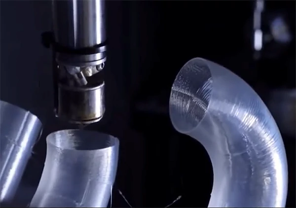
(4) Example
The FDM process is used to form a prototype with a complex surface that is difficult to process using conventional methods. After the above process flow, an injection mold cavity with high dimensional accuracy is finally obtained, as shown in Figure 6-2:
Conclusion
This chapter studies the rapid manufacturing process of injection mold cavity based on FDM prototypes and finds a simple process route: FDM prototype-post-processing-chemical Ni-P alloy plating-electroforming nickel-sandblasting roughening treatment-arc spraying Zn-A1 pseudo alloy-pouring epoxy resin backing-separation from prototype-mold cavity.
The characteristics of this process are: using optimized process parameters to electroform nickel, a nickel electroforming layer with high mechanical strength and hardness, good wear resistance and corrosion resistance can be obtained: by combining arc spraying and epoxy resin pouring, a backing with strong bonding and uniform support is obtained.
Through the example of mold electroforming of an FDM prototype with a complex surface, it is explained that the combination of chemical nickel plating, pulse electroforming nickel and FDM molding technology can achieve rapid and economical manufacturing of injection mold cavities. This process is particularly suitable for the manufacture of small and medium-sized molds with complex surfaces.
References:
- [1] Huang Qiming, Wang Yungan. Research on precision control of rapid prototyping LOM. Machinery and Electronics, 1998, (3): 34~35.
- [2] Tao Mingyuan, Han Ming. Analysis of LOM forming accuracy. Forging Machinery, 2000, (5): 12~13
- [3] P.Gu, May Yan, X. Huang, X.Zhang. Analysis of Machine Accuracy for Rapid Prototyping of Quality Components. SPIE, 1998, Vol.3517:91~101
- [4] Jack G.Zhou,Daniel Herscovici,Calvin C.Chen,Parametric Process Optimization to Improve the Accuracy of Rapid Prototyped Stereolithography Parts. International journal of Machine Tools &Manufacture,2000,Vo1.40:363~379
- [5] Zou Guolin, Research on fused deposition modeling precision and rapid mold manufacturing technology (doctoral dissertation). Dalian: Dalian University of Technology, 2002.
- [6] Qin Qixian, Guo Hetong, Liu Shulan, et al., Electroplating Principles and Technology (Second Edition). Tianjin: Tianjin Science and Technology Press, 1993.304~
- [7] Guo Huilin, Hu Xinguo, Su Guipin. Research on low temperature chemical nickel-phosphorus alloy plating process. Journal of Northwest University (Natural Science Edition), 1996, 26(4): 307~310
- [8] Feng Wanqi, Han Xiuwen, et al., Research on electroforming process of injection mold for retroreflector. Electroplating and Finishing, 2000, 22(5): 5~9
- [9] Ren Honglie, Feng Liangwei. Plastic mold manufacturing technology. Guangzhou: South China University of Technology Press, 1989.317
- [10] Zhou Xiangyang, Yang Jianhong, et al., Study on the process of electrodeposition of bright Ni-Co alloy, Electroplating and Environmental Protection, 2000, 20(3): 14~16
- [11] Qin Qixian, Li Yaomin, et al., Study on electrodeposition of Ni-Co gradient alloy, Electroplating and Finishing, 1999, 21(5): 6~8
- [12] Prasad K.D.V.Yarlagadda, Ismet P.Ilyas, Periklis Christodoulou.Development of rapid tooling for sheet metal drawing using nickel electroforming and stereolithography processes. Journal of Materials Processing Technology,200l,111:286-294