Rapid Tooling Based on CNC Machining Rapid Prototype
Five-axis CNC machining is an effective means of efficiently machining complex parts in the fields of aviation, aerospace, energy and national defense, and is a breakthrough in improving manufacturing technology. Starting from the advantages of five-axis CNC machining, describes tool path planning, geometry-mechanics integrated simulation and dynamics simulation, focusing on the recent research progress on tool axis direction optimization based on accessibility, third-order point contact and line contact forming tool position planning, tool envelope surface analytical solution and machining process stability analysis, analyzes the existing problems, and looks forward to future development trends.
Ding Han
Molds are the main tools for forming modern industrial materials. In electronics, automobiles, motors, electrical appliances, instruments, meters, home appliances, and communications, 60% to 80% of the parts are formed by molds.
The high precision, high complexity, high consistency, high productivity, and low consumption of mold-made parts are unmatched by other processing and manufacturing methods. The quality and manufacturing speed of molds largely represents the level of technological development of a country’s manufacturing industry.
After the 1990s, with the increasingly fierce market competition, manufacturers’ product development speed accelerated, and users had higher and higher requirements for product appearance.
This has led to the transformation of product production mode from traditional mass production to medium and small batch production that can flexibly adapt to the market. Under such conditions, traditional mold manufacturing technology with long cycles and low precision can no longer meet market requirements, restricting the time to market enterprise products, and thereby reducing the market competitiveness of enterprises. People have turned their attention to rapid prototyping mold technology (RPM).
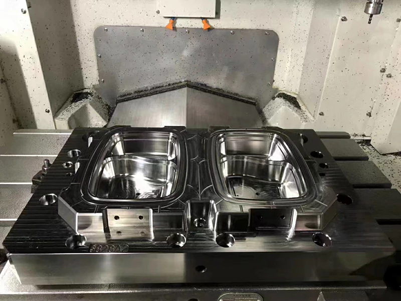
Mold Making
The RPM technology of the world’s advanced industrialized countries has gone through the stages of model and part trial production and rapid resin soft mold manufacturing and is now developing toward rapid metal tooling[1] (RMT).
In particular, the rapid prototyping technology that emerged in the late 1980s has opened up a good path for rapid mold manufacturing.
At present, many RMT methods have been proposed, which can be divided into two categories: the indirect method of rapid prototyping and replicating metal molds made by the RP system and the direct method of manufacturing metal molds directly by the RP system according to CAD data.
Direct rapid mold manufacturing refers to the use of different types of rapid prototyping technologies to directly manufacture the mold itself, and then perform some necessary post-processing and machining to obtain the mechanical properties, dimensional accuracy, and surface roughness required by the mold.
Currently, the RP processes that can directly manufacture metal molds include selective laser sintering (SLS), 3D printing (3D-P), shape deposition manufacturing (SDM) 3D welding (3D-Welding), etc.
Direct rapid mold manufacturing has its unique advantages: the manufacturing process is simple, and it can give full play to the advantages of RP technology, especially when closely combined with computer technology, to quickly complete mold manufacturing; for molds and parts that require complex shapes and internal flow channel cooling, the use of direct RT has unique advantages that cannot be replaced by other methods [2,3,4].
But in comparison, indirect rapid mold manufacturing is to manufacture molds by combining rapid prototyping technology with traditional mold remaking technology. Since these mature remaking technologies are diverse, they can use processes of different complexity and cost according to various application requirements.
On the one hand, they can better control the mold’s accuracy (up to 3.2~1.6aRµm), surface quality, mechanical properties, and service life; conversely, they can also meet economic requirements.
Therefore, most industrial sectors use indirect rapid mold manufacturing technology.
This type of technology includes spray molds, medium and low melting point alloy molds, surface deposition molds, electroplating molds, aluminum particle-reinforced epoxy resin molds, silicone molds, and rapid precision casting molds [5], which have been used to manufacture forging molds, stamping molds, die-casting molds, glass molds, etc.
However, this method requires dedicated laser-forming equipment, and the materials used to make prototypes are expensive, which limits its scope of application.
Therefore, combining CNC machining technology with precision material forming technology to develop a rapid mold technology with lower cost and shorter cycles will greatly improve the competitiveness of mold manufacturing and have great development prospects in mold industry applications.
Development trend of mold manufacturing technology
Mold manufacturing technology has developed rapidly, gradually changing from a single, specific, detailed design and processing process of each process to a systematic and integrated process of design and manufacturing technology. It has now become an important part of modern advanced manufacturing technology.
To meet the requirements of manufacturers for product development and agile mold manufacturing to meet market demand, mold manufacturing technology has also developed in the following aspects in recent years.
1) Mould CAD/CAE/CAM is developing towards integration, three-dimensionalization, intelligence, and networking
The traditional two-dimensional mold structure design has become increasingly unsuitable for modern production and integrated technology requirements.
At present, many CAD software, including surface/solid geometric modeling, complex shape engineering drawing, industrial design advanced rendering, plastic mold design expert system, complex shape CAM, art modeling and carving automatic programming systems, reverse engineering systems, and complex shape online measurement system, etc., to achieve the mold design, analysis, manufacturing three-dimensional, paperless, three-dimensional, intuitive feeling to design molds.
The three-dimensional digital model can be conveniently used for CAE analysis of product structure, mold manufacturability evaluation and CNC machining, forming process simulation, and information management and sharing.
The whole process of mold design, manufacturing, assembly, inspection, testing, and production management can be fully digitalized to achieve the best economic benefits.
2) Mold inspection and processing equipment develops towards precision, efficiency, and multi-function
The development of precision, complex, and large-scale molds has placed higher and higher requirements on testing equipment and processing equipment. The accuracy of precision molds has now reached 2~3μm.
For example, three-coordinate measuring machines can not only achieve high-precision measurements but also develop and apply reverse technology from measuring physical objects — establishing mathematical models — outputting engineering drawings — mold manufacturing.
Milling is an important means of cavity mold processing. High-speed milling has many advantages, such as low workpiece temperature rise, small cutting force, stable processing, good processing quality, high processing efficiency (5 to 10 times that of ordinary milling), and the ability to process hard materials (<60HRC). Therefore, it is increasingly valued in mold processing.
3) Rapid and economical molding technology is developing rapidly
Compared with traditional mechanical processing, rapid economical molding technology has the advantages of a short molding cycle, low cost, and high precision and service life. It is a type of mold manufacturing technology with relatively significant comprehensive economic benefits.
Rapid molding technology mainly includes rapid prototyping manufacturing (RPM), surface molding molding technology, casting molding technology, extrusion molding technology, moldless multi-point forming technology, etc. [6].
Combining RPM with traditional rapid economical molds to quickly develop and trial-produce new products has become an important development direction of rapid economical molds.
After various application discussions, RPM is vigorously developing in the direction of rapid mold manufacturing (RTM) and has made great progress.
Various rapid economical molding technologies will continue to improve, mature, and develop in the process of promotion and application. With the development of high-tech, the combination and penetration of various technologies, to adapt to different needs in production, some new, energy-saving and material-saving rapid molding technologies will be formed in the future.
4) Mold materials and surface treatment technologies are developing rapidly
Premature mold failure due to improper material selection and use accounts for more than 45% of failed molds. In terms of mold materials, commonly used cold-working mold steels include CrWMn, Cr12, Cr12MoV and W6Mo5Cr4V2, flame-hardened steels (such as Japan’s AUX2, SX105V (7CrSiMnMoV), etc.; commonly used new hot-working mold steels include American H13, Swedish QRO80M, QRO90SUPREME, etc.; commonly used plastic mold steels include pre-hardened steel (such as American P20), age-hardened steel (such as American P21, Japanese NAK55, etc.), heat-treated hardened steel (such as American D2, Japanese PD613, PD555, Swedish Assab 136, etc.), powder mold steel (such as Japanese KAD18 and KAS440), etc.;
HT300, QT60-2, Mo-Cr, Mo-V cast iron, etc. are commonly used for cover drawing dies, and HT250 is used for large mold frames. Multi-station precision punching dies often use steel-bonded cemented carbide and cemented carbide YG20, and etc.
In terms of mold surface treatment, the main trends are:
From single-element infiltration to multi-element co-infiltration and composite infiltration (such as TD method); from general diffusion to CVD, PVD, PCVD, ion infiltration, ion implantation, etc.; the coatings that can be used are: TiC, TIN, TICN, TiAIN, CIN, Cr7C3, W2C, etc.
At the same time, the heat treatment method is developing from atmospheric heat treatment to vacuum heat treatment.
In addition, laser strengthening, glow ion nitriding technology, and electroplating (brush plating) anti-corrosion strengthening technologies are also increasingly valued.
5) New processes, new concepts, and new models in the mold industry have gradually been recognized
In terms of forming technology, there are mainly stamping mold function compounding, superplastic forming, plastic precision forming technology, plastic mold gas-assisted injection technology and hot runner technology, high-pressure injection molding technology, etc.
On the other hand, with the continuous development of advanced manufacturing technology and the improvement of the overall level of the mold industry, some new design, production, and management concepts and models have emerged in the mold industry.
Specifically, they are: flexible manufacturing technology that adapts to the production characteristics of single-piece molds; team spirit that creates optimal management and benefits, lean production: parallel engineering that improves rapid response capabilities, virtual manufacturing and global agile manufacturing, network manufacturing and other new production management methods: widely adopting the division of labor and cooperative production mode of standard parts and general parts; green design and manufacturing that adapts to sustainable development and environmental protection requirements, etc.
Purpose and significance of the study
Today, the competition among enterprises is mainly reflected in the competition of product styles, new product development cycles, and product production scale. As the key tooling for the production of new products, the design and production of molds are increasingly becoming the determining factors of the new product development cycle.
In the automotive industry, the development cycle of new models used to be ten years, but now it has been shortened to two to three years. The development cycle of Ford and Toyota’s new models is only one and a half years, all thanks to the improvement of the enterprise’s mold design and manufacturing level.
With the shortening of the product development cycle, higher requirements are also put forward for the mold manufacturing cycle, so people have turned their attention back to rapid mold manufacturing technology.
Rapid prototyping technology (Rapid Prototyping & Manufacturing, referred to as RP or RPM) developed in the 1990s refers to the prototype or part manufacturing technology of complex three-dimensional entities directly driven by part CAD model under computer control and management, and using materials to accurately stack complex three-dimensional entities. It is a new rapid mold manufacturing method based on the dispersed/accumulated Forming molding principle.
This technology has been able to successfully produce prototypes of materials including resin, plastic, paper, paraffin, ceramics, etc., but it is often not used as a functional part. It can only be used to replace real metal and other types of functional parts for functional experiments in limited occasions.
It also requires special equipment and the limitations of prototype materials, which limits the wide application of this technology.
Traditional technologies such as precision casting and lost foam molding have been relatively mature after long-term development, but they cannot adapt to the rapid and flexible requirements of the information age.
Therefore, in the future, it is necessary to combine rapid prototyping technology with traditional molding technology, develop molding materials with good dimensional stability, realize the short process of the molding process and the stabilization of the working environment to improve mold accuracy and realize the agile manufacturing of rapid mold technology.
In recent years, with the development of computer control technology, computer graphics processing capabilities have been greatly developed, and automatic programming based on CAD-CAM technology for graphic interactive design has become increasingly mature.
This method has the advantages of fast speed, high precision, intuitiveness, and easy inspection, so it has been widely used in the manufacturing industry.
In the industry, whether or not to master CNC machining technology and the high or low CNC rate in the machining process have become a symbol of whether the enterprise is competitive, and have become a hot spot in mold technology research.
Therefore, this topic proposes to combine CNC machining technology with modern precision material molding technology to overcome the shortcomings of rapid prototyping technology in terms of surface and dimensional accuracy, low mechanical properties, high cost, and limited dimensional specifications, and develop a low-cost, high-precision rapid metal mold manufacturing process based on CNC machining technology.
Based on the CAD data with precise error compensation, the process uses CNC machining equipment to quickly process wax molds, foam plastic molds, or machinable polymer material molds for precision molding, and produces metal mold finished products or semi-finished products from the mold materials studied. The process route adopted is shown in Figure 1.1.

Fig 1.1
This process focuses on the precision control and early error compensation of the entire manufacturing system; research and develop a special prototype material suitable for CNC machining and precision molding, explore the rapid, high-precision machining process and precision molding process of special prototype materials; develop a mold material used for casting molds and plastic molds, and conduct preliminary research on the surface toughening and mold post-processing of the material.
Compared with the rapid mold manufacturing process based on rapid prototyping, which is currently being studied more, this process has the advantages of easier control of precision, faster speed, easy promotion, and application, and can realize the process of mold making.
Rapid mold manufacturing technology and CNC machining process
There are many traditional mold manufacturing methods, such as CNC milling, forming grinding, EDM, wire cutting, casting molds, electrolytic machining, electroplating, pressure machining, and photo etching. Due to the complexity of these processes, long processing cycles, and high costs, the response speed of new products to the market is affected.
Traditional rapid molds (such as medium and low melting point alloy molds, electroforming, spraying molds, etc.) are difficult to fully meet user requirements due to their rough process, low precision, and short life.
Rapid prototyping (RP) + rapid tooling technology (RT) will adopt the design and manufacturing methods of rapid prototyping early, multi-loop, and rapid information feedback, combined with various computer simulation and analysis methods, to form a new mold design and manufacturing system.
RP + RT can solve a large number of problems that are difficult to solve with traditional processing methods and can obtain complex shapes that cannot be obtained by general cutting processing.
It can directly manufacture complex cavity surfaces according to CAD models, and conduct new product trial production and small-batch production before the final production mold is opened. It can greatly improve the success rate of product development, effectively shorten development time, and save development costs, so it has been greatly developed [7,8,9].
1. Rapid tooling technology
According to different molding process methods, rapid tooling can be divided into direct rapid tooling and indirect rapid tooling. Direct rapid prototype molds use rapid prototype parts directly as molds, which can be used as sand casting molds, low melting point alloy casting molds, trial molding injection molds, investment casting wax molds, wax model substitutes and wax model forming molds: Indirect rapid tooling refers to using rapid prototype parts as master molds to replicate molds through cavity replication, including silicone rubber replication, metal cold spraying, precision casting, resin material strong replication, etc. [10].
1.1 Direct Molding Method
The direct method, especially the direct rapid metal mold manufacturing (DRMT: Direct Rapid Metal Tooling) method, has a simple manufacturing process and can give full play to the advantages of RP technology, especially closely combined with computer technology, and can quickly complete the mold; for molds and parts that require complex shapes of internal flow channel cooling, the direct RT method has advantages that other methods cannot replace!
However, the direct method is more difficult in terms of mold precision and performance control. Special post-processing equipment and processes have greatly increased the cost, and the size of the mold is also greatly limited.
Therefore, the key to the research and application of DRMT technology lies in how to improve the surface accuracy and manufacturing efficiency of the mold and ensure its comprehensive performance quality, so as to directly and quickly manufacture durable, high-precision and surface quality metal molds that can meet the conditions of industrial mass production.
The main DRMT methods that have emerged so far are: Selective Laser Sintering (SLS) and Laser Generating with laser as heat source; Plasma Deposition Method (PDM) or Plasma Powder Welding (PPW) with plasma arc as heat source; 3D printing (3DP) of injection molding; Shape Deposition Manufacturing (SDM) process and AIM rapid molding process developed by 3D Systems of the United States [11]
1.2 Indirect molding method
Compared with direct molding method, indirect molding method combines rapid prototyping technology with traditional mold remaking technology to manufacture molds. Since remaking technology is very mature and diverse, it can use processes of different complexity and cost according to different application requirements.
On the one hand, it can better control the precision, surface quality, mechanical properties and service life of the mold, and on the other hand, it can also meet the requirements of economy.
Therefore, indirect rapid mold manufacturing technology is widely used in the current industry. This type of technology includes spray molds, medium and low melting point alloy molds, surface deposition molds, electroplating molds, aluminum particle reinforced epoxy resin molds, silicone molds, and rapid precision casting molds.
① Spraying mold
Spraying molds include metal cold spraying molds and plasma spraying (melt spraying) molds. Metal cold spraying molds use spraying equipment from companies such as TAFA. A metal shell layer with a thickness of 2mm or even thicker is sprayed on the surface of the RP prototype with a spray gun. A mixed material of aluminum particles and resin is used as a backing material and buried in the cooling pipe.
The coating and the backing material are transferred and combined. After removing the RP prototype, the mold can be made. The replication performance of the sprayed surface is very good, the dimensional accuracy is high, and polishing can be performed to improve the surface roughness.
Plasma spraying (melt spraying) technology can be used to obtain a high melting point metal coating (such as a stainless steel coating). The mold obtained in this way has high surface hardness, good surface quality, is economical and durable, simple to make, and has a service life that greatly exceeds that of metal cold spraying molds. Takeo Nakagawa used this method to make molds with good results[12,13,14].
② Medium and low melting point alloy molds
Typical medium melting point alloys include zinc-based alloys, and low melting point alloys include Bi-Sn alloys. Casting medium and low melting point alloy molds refers to using the RP prototype as the master mold, remaking the RP prototype into a silicone mold, and then remaking the silicone mold into a plaster mold, and then precision casting the plaster mold to obtain a zinc-based alloy mold.
This process is widely used in the design of drawing molds for automobile body panels. The new process developed by Tsinghua University uses non-baking precision ceramic mold technology to complete the conversion from LOM prototype to ceramic mold, and then precision casting of low melting point alloys (Bi-Sn alloys) to obtain metal molds.
The melting point of Bi-Sn alloy is 138℃. Adjusting the ratio of Bi to Sn can control the amount of micro-shrinkage or micro-expansion during solidification, so that residual stress will not cause deformation, and high precision can be guaranteed.
The process route is: manufacture the LOM prototype according to the CAD model, remake it into a ceramic mold with sufficient dimensional accuracy, and after special treatment of the ceramic mold, cast the Bi-Sn low-melting-point alloy automobile cover drawing die at a temperature of about 140°C.
This mold can manufacture 100~300 automobile cover parts, which can fully meet the needs of automobile trial production molds.
③ Molds made by deposition technology
The principle of the RSP (Rapid Solidification Process) rapid molding technology developed by the Idaho National Engineering and Environmental Laboratory (INEEL) in the United States is to use ordinary tool alloy (such as P20, H13, and D2 tool steel or other alloy) powder to form a deposition layer with sufficient thickness on the surface of the RP prototype through deposition technology.
Under the action of supercharging, the molten metal liquid enters the nozzle. Driven by high-speed gas, the metal particles can even be deposited on the surface in an atom-increasing manner, which can replicate the extremely fine features of the RP prototype surface.
The surface roughness can reach 3μm, and the deposition rate is 227kgh. The materials suitable for this process include not only metals but also various materials such as ceramics and polymers [5].
④ Electroforming mold
Electroforming mold is a rapid mold technology that combines rapid prototyping and traditional electroforming. The process is: first, the RP prototype surface is subjected to necessary treatment, such as grinding, polishing, and coating with a conductive layer; then it is placed in an electroforming tank and electroformed at room temperature to obtain a metal shell layer, the inner surface of which accurately replicates the outer surface of the RP prototype: the prototype inside the metal shell is removed by medium-high temperature sintering; finally, a low-melting-point alloy or aluminum powder-resin mixed material backing is cast between the mold frame and the outer side of the metal shell to obtain an electroforming mold [15,16].
In addition to the above methods, foreign research and application examples include 3D Systems’ powder forming sintering + infiltration rapid replication (Kel tool) process based on SLA prototype, CEMCOM’s nickel plating + ceramic composite (NCC) process, Idaho National Engineering and Environmental Lab’s rapid solidification process (RSP, Rapid Solidification Process) and Soligen Tech. Inc.’s casting process based on DSCP metal thin shell forming system, Badger Pattern’s zinc alloy spraying + resin•metal composite material reinforcement process Tokyo University’s RHST (Rapid Hard Spray Tooling) and Nissan Motor’s rapid metal mold manufacturing method by melt spraying, etc. [13].
The process route of the Keltoo1 method is: generate rapid prototype by SLA method → silicone rubber mold to obtain the negative mold → fill metal powder and binder → put it into a high-temperature furnace for sintering and copper infiltration → obtain the final mold.
The surface hardness of the mold cavity can reach 48~50HRC after heat treatment. Molds made of A6 tool steel can produce thousands of products, but the molding process of this method is time-consuming and complex.
The NCC method first plates a layer of nickel about 1~5mm thick on the rapid prototype generated by the SLA method, and then uses chemically solidified ceramic material (CBC, Chemically Bonded Ceramic) as a backing reinforcement on the nickel coating, and separates the prototype to obtain the final mold.
This method has the same accuracy as the SLA process and can be used for injection mold manufacturing, but it needs to solve the problems of long electroplating process time and waste liquid pollution.
The RSP method uses high-speed inert gas to atomize the molten metal liquid and shoot it on paraffin, plastic, or ceramic prototypes (made by SLA, SLS, or LOM methods) to generate a thin layer of metal, reinforce the backing, and remove the prototype to obtain the mold.
This method can make injection molds and stamping molds, but in order to improve the surface quality and mechanical properties of the parts, aging treatment is required, which increases the molding time.
The basic process of the spray tooling method of Bafger Pattern, Tokyo University, and Nissan Motor Company is to form a spray layer on the prototype surface, then reinforce the spray layer and remove the spray prototype to obtain a metal mold.
However, Bafger Pattern can only spray low-melting point zinc alloy and use resin-metal composite materials to reinforce the spray layer, resulting in poor wear resistance and thermal conductivity of the mold, which can only be used for injection molding of hundreds of pieces.
The RHST method developed by the University of Tokyo uses high melting point materials such as stainless steel or tungsten carbide alloy as the spray material and reinforces the spray layer backing with metal materials, thereby greatly improving the durability of the spray mold, making it applicable to mass injection molding of plastic products with smooth surfaces or natural fine leather patterns, as well as metal sheet forming.
Nissan Motor’s spray tooling method also uses stainless steel as the spray material and uses resin-metal composite materials for reinforcement, which has been used to form car covers of tens of thousands to more than 200,000 pieces.
However, compared with the RHST method, this method cannot be used to manufacture durable injection molds with natural fine leather patterns on the surface, and its scope of use is limited.

1.3 Comparison of Rapid Tooling Technologies
Since there are many types of rapid tooling technologies and manufacturers have a wide range of choices, it is necessary to compare rapid tooling manufacturing technologies. Table 2.1 lists the relevant performance parameters of several rapid tooling methods, Table 2.2 shows the comparison of mold life, Table 2.3 lists the comparison of mold costs, and Table 2.4 shows the comparison of production cycles.


2. CNC machining technology
2.1 Characteristics of CNC machining
CNC machining, also known as NC (Numerical Control) machining, is the process of digitally expressing the parts to be processed, and numerical control machines digitally control the movement of tools and parts to achieve the process of part processing[17]. After half a century of development, CNC machining technology has become an advanced manufacturing technology used in various contemporary manufacturing fields. The biggest features of CNC machining are the following two points: First, it can greatly improve the accuracy, including the accuracy of machining quality and the accuracy of machining time error; second, the repeatability of machining quality can stabilize the machining quality and maintain the consistency of the quality of the machined parts. In other words, the quality of the machined parts and the machining time are determined by the CNC program rather than the machine operator. Specifically, CNC machining has the following advantages:
- 1. Improve production efficiency;
- 2. No need for skilled machine tool operators;
- 3. Improve machining accuracy and maintain consistent machining quality;
- 4. Reduce tooling and fixtures;
- 5. Easy to manage the machining process;
- 6. Reduce scrap and defective rates;
- 7. Reduce inspection workload;
- 8. Facilitate design changes and flexible machining settings;
- 9. Easy to automate the operation process, one person can operate multiple machine tools;
- 10. Easy to operate, greatly reducing the intensity of physical labor.
Although CNC machining has the above advantages, its equipment is expensive and the processing preparation cycle is long. Therefore, CNC machining also has its scope of application:
(1) Most suitable for CNC machining parts:
parts with complex shapes, high processing accuracy requirements, parts that cannot be processed by ordinary machine tools or parts that can be processed but it is difficult to ensure product quality; parts with complex curve wheels or complex surfaces; shells or box-shaped parts with inner cavities that are difficult to measure, difficult to control feed, and difficult to control size; parts that must complete multiple processes such as milling, boring, and reaming in one clamping;
(2) More suitable CNC machining parts:
In general, Parts that are easily disturbed by human factors when processed on general-purpose machine tools and whose materials are expensive; parts that must have complex special tooling on general-purpose machine tools; parts that require multiple design changes before they can be finalized; parts that require long-term adjustment when processed on general-purpose machine tools; parts that have low production efficiency or high physical intensity when processed on general-purpose machine tools;
(3) Unsuitable Parts processed by CNC:
parts that are difficult to clamp or rely entirely on alignment to ensure processing accuracy: parts with very unstable processing allowances and parts on CNC machine tools that do not have an online detection system that can automatically adjust the coordinate position of the parts.
2.2 CNC machine tools
In the decades since the first CNC machine tool was put into use in 1957, CNC machine tools have been computer-controlled and widely used in the industry, becoming a symbol of the modernization of the manufacturing industry.
There are many types of CNC machine tools. Various types of CNC machine tools have been developed to meet the requirements of metal cutting processes such as turning, milling, grinding, drilling and planing, as well as special processing processes such as electrical processing and laser processing. Commonly used in the mold manufacturing process are: CNC milling machines, CNC EDM forming machines, CNC EDM wire cutting machines, CNC grinders and CNC lathes.
In CNC machining, CNC milling machining has the characteristics of high productivity, machining accuracy, multi-axis linkage, ability to process complex shapes and strong machining adaptability. As long as the machining program is input, parts of different shapes can be processed.
Therefore, it is particularly suitable for single-piece or small-batch mold manufacturing. The main mold industries are: plastic injection molds, plastic compression molds, light metal die-casting molds and forging molds, etc., which have complex curved surfaces and contours. The representative parts are cores, cavities, electrodes and mold parting surfaces required for EDM machining cavities.
Before the emergence of CNC milling, the processing of such parts could only rely on operators to use ordinary machine tools to perform semi-finishing or finishing on the parts with a margin, and the remaining machining margins were corrected and removed by skilled fitters.
This manual operation method is difficult to guarantee the geometric shape and machining accuracy of the parts. Even if skilled operators can achieve the required shape and accuracy, the processing time is expensive, and it is difficult to guarantee the quality of the processing.
2.3 CNC machining process
In CNC machining, the processed parts are represented by wireframes, surfaces, entities, and other geometric bodies in the CAD system, and the tool path is generated in the CAM system. After post-processing, the machining code is generated, and the machining code is transmitted to the CNC machine tool through the transmission medium.
The CNC machine tool digitally controls the tool movement to complete the part machining. The process is shown in Fig 2.1.
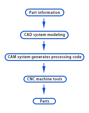
Fig2.1 Numerical control machining process
2.4 Application of CNC machining technology in molds
A wide variety of CNC machining methods provide more production means for mold machining. According to their characteristics, molds can be divided into many categories. In actual production, according to the different mold manufacturing and processing characteristics, the most appropriate processing method is selected to reduce costs and improve production efficiency.
For rotating parts, CNC turning is generally used, such as turning outer circles, turning holes, turning planes, etc., and molds such as wine bottles, wine glasses, and steering wheels can all be processed by CNC turning.
For molds with complex contours or curved surfaces, electrodes for EDM are generally processed by CNC milling. Such molds, such as injection molds and die-casting molds, are all processed by milling.
For molds with fine and complex shapes, special materials, plastic inlaid cavities and inserts, and molds with special-shaped grooves, CNC EDM wire cutting can be used.
The mold cavity and hole can be processed by CNC EDM, including various plastics, rubber molds, forging molds, die-casting molds, calendering and stretching molds, etc. For geometric surfaces with high precision requirements, CNC grinding can be used. Cavity and core processing mainly rely on milling and EDM.
In terms of milling, ordinary milling, various types of CNC milling, CNC copy milling, machining center processing, etc. are currently widely used; in terms of EDM, various types of ordinary EDM and CNC EDM (NCEDM) have also been widely used in various industrial countries.
3. Relationship between rapid Tooling and CNC machining technology
Due to market globalization and intensified competition, the mold market’s most important and prerequisite requirement for each mold technology is its rapidity, that is, the time from design to market entry (Leading time), which is the fundamental reason for the emergence and development of RP+RT technology. The market’s requirements for molds are comprehensive, including precision, materials, life, size, shape complexity, and rapidity.
Due to the difficulty of depositing metals (ferrous metals, non-ferrous metals, and their alloys, etc.), direct RT technology, which directly manufactures molds using RP, will not be widely used in the RT field in the next five or six years. With the improvement of high-power laser sintering, laser coaxial powder feeding, three-dimensional welding, uniform droplet injection (UPS), and other laser net forming technologies, it is estimated that direct RT technology will gradually become the mainstream of RT technology within 10 years. There are three reasons why direct RT is favored by many professionals:
•Mold companies hope to eliminate the process of making mold prototypes (Pattern) and prototype post-processing to improve speed;
•Precision will be lost through prototype conversion, which complicates the compensation control of precision;
•The mold life of indirect RT production is often lower, which is also one of the reasons why it is at a disadvantage in the competition.
RT’s external competitive technology is high-speed machining technology (HSM-High Speeds Machining). In fact, HSM and RT are both types of technologies supported by CNC technology. However, the former is digital-analog processing, that is, digital technology only supports the control of tools, and the materials being processed have nothing to do with digital technology.
Therefore, it is impossible to complete the processing of more complex shapes (such as molds with internal flow channels), nor can it manufacture molds with functional gradients and material gradients. It can only be cutting processing of the same material.
RT is a technology based on the dispersed/accumulated forming principle. Digital technology not only supports the control of tool trajectory movement but also can directly involve the material itself.
Digital technology will control the type, formation, morphology, and movement trajectory of droplet materials, and the mutual connection between droplets. Therefore, this is digital manufacturing in the true sense.
This essential difference determines the long-term vitality and fundamental competitive advantage of RT. It can complete the direct manufacturing of complex internal flow channels and can manufacture better tools and molds with material gradients and functional gradients.
This essence is a competitive advantage, accelerating the development of RT. It is also the principle of dispersed/accumulated that limits its current accuracy and surface roughness, making it still have many technical problems to solve in the competition with HSM.
However, RT must seek development space in the competition with HSM. The status of RT and HSM in digital manufacturing is beneficial. Many rapid tooling companies use both RT and HSM technologies at the same time, taking advantage of their complementary characteristics.
From the fundamental direction of the development of manufacturing science, the dispersed/accumulated production line and the five-axis CNC electrolytic machining machine tool of GE Company in the United States show that computer control technology will expand the application and research of electrolytic machining in an important development direction.
Research on prototype materials and their CNC machining technology
Prototyping is one of the most important factors in product development and manufacturing, it is conducive to the verification of the product as soon as possible and put into production manufacturing, with the traditional method of making samples, the need to use a variety of mechanical processing machine tools, as well as molds and tools, but also a high level of skilled workers, not only time-consuming, costly, the cycle is often up to a few weeks, or even a few months, and can not adapt to the current product ever-changing changes.
RPM technology can quickly manufacture product prototypes or molds, but the cost is too high, and the accuracy often fails to meet the expected requirements.
Traditional such as investment casting, solid casting (disappearing mold casting), plaster casting and other precision casting methods compared with sand casting have unique technical advantages: high dimensional accuracy of castings, and surface roughness.
Castings of high dimensional accuracy, low surface roughness, dimensional accuracy of up to CT4 ~ CT7, surface roughness generally up to 1.6μm, adapted to the multi-species, single-piece and mass production as well as geometrically complex small and medium-sized castings, in addition to the need for mechanical machining of the surface of the rest of the parts of the shape of the tolerance and surface roughness do not need to be processed to meet the requirements.
Solid casting is called the most advanced, promising technology due to its casting materials, casting size, production batch, and complexity with good adaptability.
The prototype material foam is made of synthetic resin with porous honeycomb organization inside, lightweight, soft texture, low strength, and poor thermal conductivity, from a wide range of sources and easier than paraffin wax for CNC machining, so it has great potential for development as a prototype material for CNC machining.
1. Selection and preparation process of raw materials for the mold [18]
1.1 Selection of prototype materials for molds
① Comparison of wax material and foam material
In investment casting, investment casting by melting mold is a less-cutting process, which has the advantage of producing high-precision and high-finish castings. However, wax as a prototype material has the following shortcomings:
1. Size and shrinkage problem:
Wax material has a large thermal expansion rate, which is greatly affected by the thickness and shape of the mold. The larger the size and shape of the paraffin wax prototype, the more pronounced the deformation, resulting in a loss of accuracy.
2. Size limitation:
the maximum casting weight of wax mold is not more than 30kg and the maximum length is not more than 300mm, which is only suitable for small and medium-sized castings.
3. Strength and handling problems:
low strength and low specific gravity of wax material (about 1) make it difficult to coat large wax molds. Wax softening temperature is low, there needs to be strict control of the operating temperature, otherwise easy to deform and soften.
4. Complicated process:
The investment casting process is complicated, with many procedures, a long production cycle, and high costs.
5. Expansion and contraction problems:
wax mold expansion and contraction rate are large, good quality wax line contraction rate is still up to 0.6% ~ 1.2%, generally 1% ~ 3%.
6. Processing problems:
wax molds are prone to cracks during CNC machining.
In contrast, polystyrene foam has high deflection temperature, low density, high strength and low line shrinkage. Its density and strength are adjustable to suit different applications. As density increases, strength rises, surface finish improves, and line shrinkage and deformability decrease. Tables 3.1 and 3.2 demonstrate the comparison of physical properties and other parameters of foam and paraffin as model materials.

② Conditions for Foam Modeling Materials
Good foam modeling materials need to have the following conditions:
1. low density and low vaporization temperature:
the density is as small as possible, with low vaporization temperature, less heat absorption during vaporization, and a small amount of gas and smoke during pouring.
2. sufficient strength and stiffness:
in the case of low density, still has enough strength and stiffness to ensure that the mold manufacturing, handling, and modeling process is not easy to damage, size, and shape stability.
3. easy cutting:
uniform holes, dense structure, and easy to process and repair.
4. Appropriate gasification speed:
to ensure that the liquid metal is smoothly poured into the cavity, complete gasification, and less residue, to avoid casting slag defects.
5. good adhesion:
good adhesion with refractory coatings.
6. Harmless gas:
no harmful gas is produced after gasification, avoiding environmental pollution.
Polystyrene foam has become the most commonly used mold material, with the advantages of light specific gravity, rapid gasification, less residue, easy molding and processing, abundant resources and inexpensive. The key to ensuring the quality of Lost foam casting products is to use high-quality casting special foam beads. Packaging foam made of foam model will be due to the amount of gas and carbon increase and other factors affect the quality of casting products.
There are three main types of special foam beads for lost foam casting.
1. dispersible polystyrene resin beads (EPS) for vanishing mold casting.
2. foamable methyl methacrylate and styrene copolymerization resin beads (STMMA).
3. Expandable poly(methyl methacrylate) resin beads (EPMMA).
Table 3.3 lists the scope of use and physical properties of three types of beads produced by a specialized manufacturer.

1.2 Manufacturing process for polystyrene bead pellets
Polystyrene foam is divided into two categories:
1. expandable polystyrene produced by suspension polymerization of granular polystyrene resins.
2. polystyrene foam produced by emulsion polymerization of powdered polystyrene resin.
Expandable polystyrene foam is mainly used in casting. The process flow of foam production is shown in Figure 3.1.
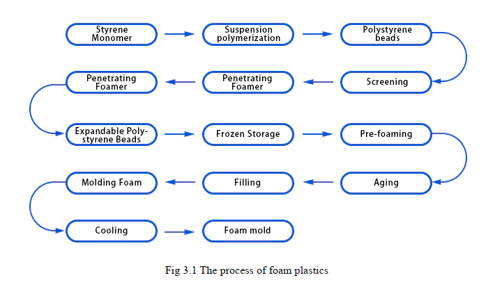
① Manufacture of Expandable Polystyrene Beads
Styrene monomer of more than 99.5% is used in the production. Put it in a stainless steel reactor with a stirrer, add 2~3 times the soft water of styrene monomer, add another appropriate amount of initiator BPO (benzoyl peroxide dissolved in styrene) and dispersant PVA (polyvinyl alcohol), etc., and heat it up to 80~90 ℃ to react for 8~10 hours. Formed and hardened after heating to 100 ℃ above the ripening of 3 hours to produce a diameter of 0.3 ~ 3mm slightly transparent polystyrene beads.
② Process Flow of Expandable Polystyrene
1. Charging: the screened beads are transported to the reactor through the pipeline, soap powder is also added to the kettle when charging, and the blowing agent is sucked into the high metering tank with a reciprocating pump and put into the kettle. 2.
2. kettle operation: after feeding, heat the kettle to pressure 1MPa, keep warm for a certain period of time and then cool down to below 40℃ and discharge.
3. cleaning, blow-drying and packaging of beads: wash the foaming beads, filter water for one day and blow-dryer drying, packaging and storage.
③ Defects in the production of polystyrene bead pellets and solutions (see Table 3.4)
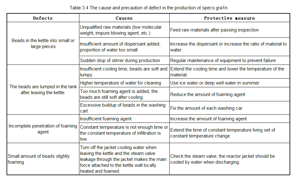
④ Performance of expandable polystyrene beads and grains
Polystyrene is colorless and transparent, soluble in aromatic hydrocarbons. Under normal conditions, the density of polystyrene bead grain is 1.05g/cm³, the glass transition temperature is 80℃, and it is elastic at 80~90℃. The remaining styrene monomer contained within the bead grain increases plasticity, but more than 0.5% will stick in the pre-foaming stage. The quantity, distribution, and composition of the blowing agent affect the foaming speed, pore organization, and mechanical properties.
1.3 Pre-foaming of polystyrene beads
① Pre-foaming mechanism
Polystyrene beads are slowly heated to 80 ℃ (glass transition temperature) before not foaming, only the blowing agent to escape, the beads themselves do not expand. The temperature rises to 80 ℃ or more, the beads into a rubbery state, and the blowing agent is vaporized by heat to produce pressure, the formation of honeycomb-shaped holes.
② Pre-foaming process and classification
According to the different heating media, the pre-foaming method has six: infrared pre-foaming, hot air pre-foaming, high-frequency pre-foaming, hot water pre-foaming, steam pre-foaming, and vacuum pre-foaming. Among them, steam pre-foaming has the advantages of low labor intensity, continuous production, high yield, easy operation, and quality control, and is the most commonly used method. The process of adding materials, reactor operation, cleaning blow-drying, and packaging.
③ The main factors affecting the quality and performance of pre-fired bead particles
1. Pre-emergence time: prolong the pre-emergence time, the mold strength decreases, the density drops to the lowest value, and then back up. (See Figure 3.2)

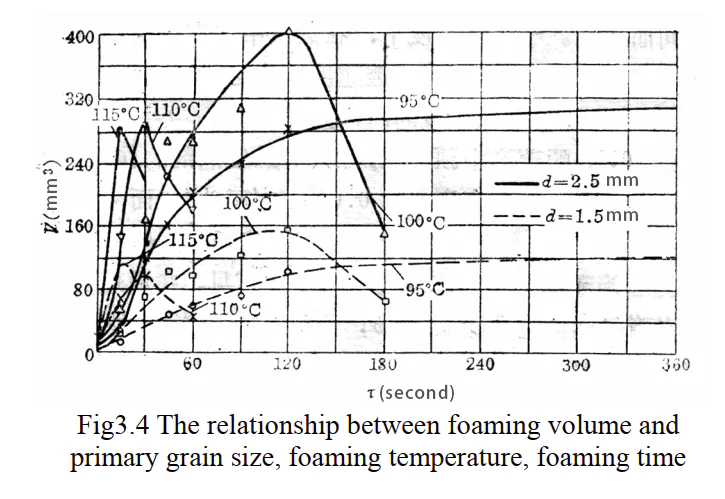
2. Pre-emergence temperature: lower than the glass transition temperature beads do not expand, with the increase in temperature expansion rate accelerated (see Figure 3.3), to reach the minimum density time becomes shorter. In addition, the heating temperature of the pre-foaming medium of the heating temperature also affects the speed of pre-foaming, as shown in Figure 3.4.

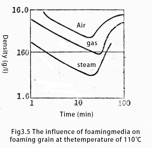
3. Heating medium: foaming medium has a great influence on foaming, steam is the best foaming medium. At a temperature of 110 ℃ when the effect of different media on the foaming of beads. As shown in Figure 3.5.
1.4 Foam polystyrene beads ripening
① Ripening Mechanism
After pre-foaming, the beads need to be matured, dried, and ripened to ensure the elasticity and expansion capacity of the beads. Too high temperature increases the loss of the blowing agent, too low temperature limits the reabsorption of the blowing agent and air depth, and the optimal temperature is 20~25℃. Cooking time is related to humidity and density, and low-density ripening time is long.
② The main factors affecting the ripening
1) Ripening temperature
Temperature has a great impact on the ripening. Too high a temperature will increase the loss of the blowing agent, too low a temperature will limit the reabsorption of the blowing agent and the depth of air. The most suitable temperature is 20~25℃.
2) Ripening time
Ripening time is related to the humidity and density of the pre-foamed beads. The drier the bead grain, the air to the bubble hole penetration rate is, and the shorter the maturation time; pre-foam bead grain density the lower the maturation time is. In addition, the ripening time is also affected by the ripening temperature and method. Table 3.5 lists some of the relationships between density and ripening time[18].

1.5 Molding foam and cooling process
① Molding of foam molds
1. Molding equipment: Molds are divided into combination molds and integral molds according to the structural characteristics and precision requirements of foam parts. Aluminum alloy molds are widely used in the production of molded parts.
2. Molding process: including charging, heating, foaming, shaping and cooling. Temperature and time need to be controlled during foaming to ensure uniform foam and fine pores.
② Foam mold cooling
1 cooling equipment: including water chillers and cooling towers, etc. 2 cooling process: foam molding molding.
2. Cooling process: the foam mold needs to be cooled immediately after molding to prevent deformation and shrinkage of the mold at high temperature. Cooling time and method should be chosen reasonably according to the structure and thickness of the mold.
Figure 3.6 shows the molds used in the test process and the foam polystyrene samples obtained by foam molding.

Fig3.6
2. Mold CAD process design[19]
Computer Aided Geometric Modeling is a technology that uses computers and their graphic tools to describe the shape of objects, design geometric shapes, and simulate the dynamic processing of objects.
The main research free curve surface representation, design, modeling display, analysis, and processing issues, is the basis of geometric modeling methods. Many of the current CAD modeling software (such as UG, PROE, etc.) are toward the development of feature modeling direction, generally having form features, precision features, material features, and technical features (Technical Feature) in four parts. The four parts of Precision Feature, Material Feature, and Technological Feature.
Form feature refers to the geometric abstraction of engineering significance; precision feature refers to the product’s nominal geometry of the allowable error, including dimensional error, shape tolerance surface roughness, etc., to determine the processing of products when the cutting speed, process parameters; material features refers to the product with the material type, grade, heat treatment requirements of the process parameters; technical features are related to the product’s performance indexes, operating specifications and other aspects of the Information.
In CAD software in the completion of product modeling and molding, the characteristics of the product must be carried out in the mold process design, such as the setting of risers, shrinkage allowances, draft angle, and so on.
In the mold design, not only to consider the shrinkage allowance of the mold material but also to consider the shrinkage allowance of the subsequent precision casting process. After determining the process parameters, surface parting is carried out to obtain the mold, and then set the position of the top bar, and so on.
For the mold design of large molds, after setting up the process parameters, CAE simulation software is used to carry out numerical simulations of the process to achieve the optimization of the process.
After completing the mold design, set the processing parameters, simulate the processing and generate NC data under the CAM module, and finally transfer to the CNC machining center to complete the processing of the mold.
Figures 3.7 and 3.8 show the 3D model of the water inlet pipe, which is modeled in UG and prepared for CNC machining.


3. CNC machining process for foam moldings
3.1 Basic principle of cutting and machining of foam [18,20]
Since foam is a porous honeycomb organization with light specific gravity, soft texture, low strength as well as poor thermal conductivity, the machining of foam can not be like the machining of hardwood or metal materials, nor can the machining principle of cutting metal be used to explain the cutting process of foam.
Usually, the essence of the cutting process of metal is the extrusion process. The soft and fragile foam in the extrusion process is easy to breaks in the weak points of the organization or causes the foam particles the peel so that the processed surface is rough and uneven to achieve the foam into a smooth surface, which can only be based on the characteristics of such materials, according to the “Phi cutting” principle for processing.
“Phi cutting” means that the surface of the processed foam and the cutting tool in the cutting process at a certain angle, both at a certain speed relative to the process of movement of the sharp edge of the knife will be plastic surface cutting down the process (as shown in Figure 3.9).
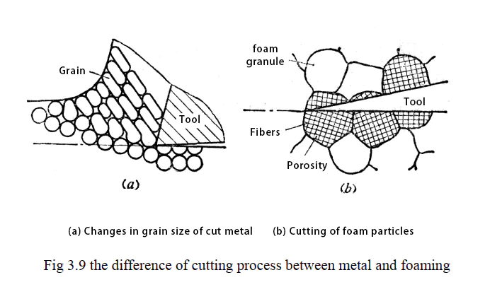
Cutting process, when the blade of the cutting tool part in contact with the foam at the moment, the foam-like surface layer produces small cracks and cuts, the knife to a certain cutting angle and very fast cutting speed to continue to extend the expansion of the cut and the blade in contact with the part of the bubble pore organization, constituting a localized processed surface.
3.2 Processing technology of foam[21,22]
Foam processing equipment, according to the processing method is divided into the main milling machine, lathe, inside and outside the round sanding bed and a hand-push flat planer, etc.; there are also desktop foam winding saw machines, vibration-type foam planing machines, and electric wire cutting machine and other special equipment.
Cutting foam cutting tools can not be used to cut metal and wood cutting tools, but should be used edge and sharp special tools.
To ensure the dimensional accuracy and finish of the mold, generally, the slabstock foam blank should be first planed and cut out the flat and straight reference plane on the hand-push flat planer or electric wire cutter, and then choose the suitable method for finishing.
① Milling
Milling is one of the most commonly used methods in CNC machining, which is mainly used for machining flat surfaces, curved surfaces, internal holes, and rounded corners.
The quality of the surface of foam processing depends largely on the structure of the milling cutter as well as the milling method and process parameters.
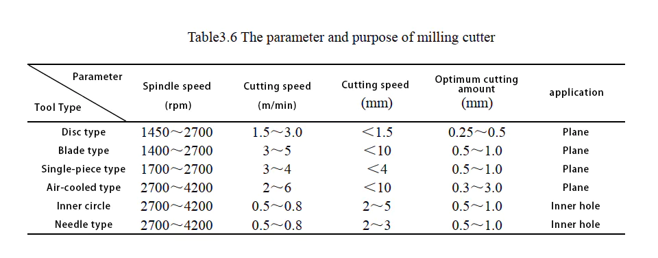
When processing foam, different milling cutters and process parameters should be selected according to the equipment and processing requirements. If the cutters and parameters are not properly selected, it is easy to happen that the foam particles are peeled off or the processed surface is roughening. At present, the common milling cutters and main process parameters used for cutting foam in China are shown in the following table (see Table 3.6) [18].
In the CNC milling process, after a long time of processing, there will be a sticky cutter phenomenon, easy to produce arc-shaped bristle traces on the machining surface. Therefore, it is also necessary to frequently clean the cutter edge during processing, which will also affect the cutting efficiency.
The main reason for the sticking phenomenon of the chip foam mold is that the thermal conductivity of the foam is very poor, low softening temperature, the cutter edge will make the molten polystyrene adhere to the cutter edge with a little heat (> 75 ℃). The use of a sharp and polished blade can reduce the blade temperature, but its effect is limited. A direct and effective method is to cool the knife blade directly.
The use of an electric fan or hair dryer to cool the cutter blade during the tests revealed a significant improvement in the surface quality of the processed foam, but this interfered with the operation. Air-cooled foam surface milling cutters developed in the literature utilize the airflow generated by the high-speed rotation of the cutter and the relative motion of the air to cool the cutting edge [18,23].
Due to the soft texture of the foam and the low cutting forces, no fixturing is required during the milling process even for machining large moldings, which can be done by using the clamping device on the CNC machine or by pressing with a heavy object. The surface finish of the milling foam depends largely on the structure of the milling cutter and the sharpness of the cutting edge, as well as the cutting process parameters.
When milling flat surfaces, the spindle speed is generally 1500~3500 rpm and 3000 rpm is preferred. The processing of rounded corners, and inner circle, often controlled at 2700 ~ 4200 rpm, to 4200 rpm is appropriate. Because the milling cutter in the slower speed will scrape down the foam, the machining surface strains.
To reduce the machining deformation of the parts, the following control methods are used.
1) Reduce the amount of machining each time, that is, the machining of the profile is divided into roughing and finishing, the first in the ordinary machining equipment to remove most of the allowance; in the roughing, with a large tool (25 ~ 30mm), large row spacing (60% – 80% D), large tolerance machining, leaving a finishing allowance of 3mm; finishing, with a suitable tool, small row spacing (20% – 50% D), small cut layer (1 ~ 2mm), small tolerance machining, with a suitable tool, small row spacing (20% – 50% D), small cut layer (1 ~ 2mm), small tolerance. 2mm), small tolerance machining.
2) Select the appropriate tool, roughing with coarse teeth, large cutting angle of the tool, finishing with fine teeth of the tool: shape, roughing with a flat end mill, finishing with a rounded end mill or ball cutter: the depth of the size of the large parts, to avoid tool chatter affecting the machining accuracy, the application of LD small tool.
3) Adopt a reasonable machining process, the last machining of high requirement profile, eliminating the machining deformation, and several times of flanging can also release most of the machining deformation.
4) Use the correct clamping method, in addition to the use of CNC machine tools on the clamping fixture, you can also add fixed bolts inside the foam prototype to increase the low resistance to deformation. For CNC machining milling machine power is small, rigidity is not good, the stroke is not enough, and other shortcomings, you can also use segmented processing methods for processing: according to the depth of machining, the selection of the appropriate tool, the machining track is divided into several segments, such as some of them are divided into three segments of machining, the more complex profiles are divided into four segments of machining because it is easy to achieve with the cavity milling of the cut layer control supplemented with a text editor [24].
②Grinding Processing
Usually used for grinding processing grinding machines and CNC processing machine tools can be used for grinding foam. Grinding foam should choose to use the grinding head with fine abrasive grains, the feed amount should not be too large, otherwise, it will intensify the friction heat so that the surface of the foam produces a serious bonding phenomenon and the formation of a layer of crust, the main reason is that the surface of the foam is localized softening and melting and compaction. As in the case of machining metals, the surface roughness of the mold after chipping is superior to that of the milling method. For foam molds with higher roughness and accuracy requirements, specially designed air-driven sanders can be used for grinding [18].
3.3 Defects of mold molding by CNC machining and their solutions
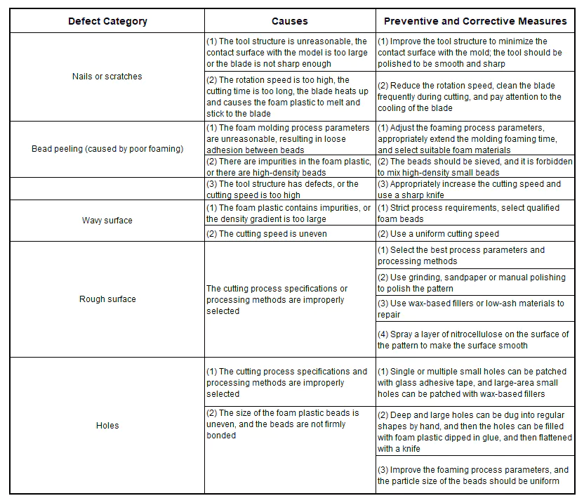
When machining the mold with the CNC machining method, due to the unreasonable shape of tool structure, improper selection of process parameters negligence of operation, and poor quality of foam, the surface of machined foam may produce defects such as surface scuffing, bead shedding, undulating concave-convex surfaces and small holes, and in serious cases, the mold may even be scrapped.
Therefore, analyzing the causes of defects will help to take effective measures to improve the processing quality. Common defects and their elimination measures are shown in Table 3.7.
4. Factors affecting the quality of foam and surface treatment
4.1 Factors affecting the quality of the foam model
The surface quality of the foam model, in addition to the processing method, the structure of the cutting tool, the operator’s skills, and the foaming process, but also with the mold material polystyrene beads component, the specific gravity of the foam and the density of the pore size, as well as the structure and roughness of the mold, the mold cooling method and foaming agent.
Because the appropriate density and reasonable foaming process to get a dense, uniform pore size of the foam sample, to process the surface of the parts of the surface of the curved profile.
At the same time, only suitable cooling methods, cooling time and surface clean mold or surface quality meet the requirements of the foam prototype.
① Influence of bead components on mold quality
The process specification of pre-foaming and molding foaming of polystyrene beads, as well as the quality and performance of the resulting molds, depend on the monomer content of polystyrene beads and the molecular weight of polystyrene matrix, as well as the particle size composition of the beads and the specific gravity of the heap and other factors.
The presence of residual styrene monomer in the bead grain increases the plasticity of the polystyrene matrix. However, when the content exceeds 0.5%, undesired bonding occurs at the pre-foaming stage, and lowering the content of the residual monomer causes the pre-foaming and molding foaming temperatures of the bead grains to move in a high direction.
In addition, styrene ethyl monomer is toxic, so the content of styrene monomer in virgin beads should be limited to between 0.01 and 0.025%. With the increase of molecular weight, the mechanical properties and heat resistance of the foam are improved, while the present shrinkage is reduced and stabilized accordingly, and the processability and quality of the foam sheet are also improved.
② Factors affecting the surface roughness of the foaming mold
Foam mold surface roughness in addition to the foaming process, to a certain extent, depending on the mold mechanism and the cavity surface roughness, as well as the particle size and density of the beads. The better the surface roughness of the mold cavity, the better the surface roughness of the foam mold. The surface roughness of the foam mold is one level worse than the roughness of the mold cavity.
In addition, the presence or absence of air holes or air plugs on the mold, as well as the size and shape of the air holes and air plugs, are factors that directly affect the surface roughness of the mold. The smaller the polystyrene pre-generated particles, the greater the density, the greater the expansion, the greater the density of the foam sample or plate: the surface roughness of the prepared mold is also closer to the surface roughness of the mold cavity.
And the mold with high density has dense internal structure, fine pore size and high surface finish after CNC machining. So for the CNC machining of foam, the density of the mold is generally controlled at 0.1~0.3g/cm3.
③ Density gradient of foam molding
The general effective penetration density of steam is about 80~100mm, if the steam is introduced from one wall of the mold, and at the same time discharged from the other wall of the relative, the thickness of the mold is more than 80mm, there will be a density gradient (i.e., the density of the mold cross-section of the distribution is not uniform); the density of its surface layer to the center of the part of the gradually decreasing, and the bubble holes are also gradually coarser. Roughness after CNC machining is also inevitably better than the surface of the internal.
Therefore, to obtain the processing effect of uniform surface quality, try to request the approximate uniform density of the mold.
④ Control of hole size, density, and uniformity inside the foam mold
If the internal aperture of the mold is dense and uniform, the processing surface with a high finish can be obtained after processing. Therefore, the density and uniformity of the internal aperture of the mold is one of the important factors for obtaining a good processing surface.
To ensure that the foam mold internal aperture, density, and uniformity, in addition to strict control of beads in the production of screening quality assurance particles in addition uniformity, also through the pre-foaming process (mixing speed, steam pressure, and temperature) and the structure of the pre-foaming machine to ensure that access to as uniform as possible to the pre-foaming beads; in addition to through the heating time and temperature molding conditions, change the structure of the mold and its distribution of air holes and the number of improved to get a good foam mold.
4.2 Surface treatment process of mold pattern
Since the shape of the foam prototype mold is directly related to the accuracy of the subsequent process and the accuracy of the final mold, it is important to ensure the surface quality of the foam.
In addition to the aforementioned control of the intrinsic quality of the foam mold, after the CNC machining should also carry out the necessary follow-up treatment to improve the surface quality of the mold, such as in the process of machining the CNC prototype, due to poor foaming or poor molding process will produce very small holes on the surface of the prototype, if not remedied in time, these defects will be truly reflected in the metal mold.
Therefore, it is necessary to coat the surface of the CNC prototype with a layer of special coating that can fill such surface defects to improve the surface roughness of the mold.
Surface finishing coatings for filling shall meet the following requirements.
(1) good elasticity and film-forming properties.
(2) Good flowability and quick drying.
(3) Does not penetrate the refractory coating and sand mold.
(4) No erosion of foam molding.
(5) Complete vaporization and low residue.
(6) Harmless to metallic fluids and no other public hazards.
(7) Good adhesion property to the foam molding.
(8) Sufficient supply of raw materials and low cost.
(9) Convenient preparation and coating operation.
The surface finishing coatings that satisfy the above conditions are commonly used in two categories: stearic acid, paraffin coatings, and nitrocellulose coatings.
The test used paraffin-stearic acid coating, the basic formula is: using 40% stearic acid, paraffin 10% as solute: 43% industrial alcohol, benzene 7% as solvent. First of all, the stearic acid (melting point 57 ℃) and paraffin wax (melting point 56 ℃) mixed with heating, to be dissolved and slowly added to the prepared solvent, while adding and stirring into a milky white paste can be used.
Although the wax coating can fill the pores and small holes, there are some disadvantages as follows.
(1) Raw materials are more expensive and consume more materials, which increases the cost.
(2) It leaves residue after burning, which is unfavorable to the subsequent process.
(3) The process is cumbersome, and the wax must be melted before it can be coated.
Therefore, for the repair of gaps and small holes in the production, more often than not, glass adhesive paper is used to cover the gaps and small holes: for the larger voids and damages, the foam is generally processed into the corresponding shape and then nailed on the molding with big head nails, nails, or connected with the bonding agent.
Precision casting process based on CNC prototype
After obtaining a prototype with good surface quality through CNC machining,In order to minimize the accuracy loss during the prototype conversion process and simplify the accuracy compensation control, It is also necessary to select a precision casting technique to obtain the metal type mold.
In the current precision casting technology, The Plaster investment casting technology has the advantages of producing large thin-walled castings, especially suitable for aluminum alloy castings, etc, Therefore, it is widely used in rapid mold manufacturing. Table 4.1 lists the comparison of three precision casting methods [25].

1. Technological characteristics of plaster casting
1.1 Plaster mold precision casting process
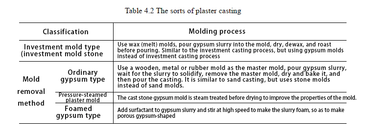
Gypsum mold precision casting can be divided into two categories according to the different casting processes (see Table 4.2). The specific process flow is shown in Figure 4.1.

1.2 Technological characteristics of plaster casting
Plaster casting is suitable for producing precision castings with precise dimensions and smooth surface, It is particularly suitable for the production of large, complex, thin-walled aluminum alloy castings, and can also be used for zinc, copper, gold and other alloys. The maximum size of the casting can reach 1000mmx2000mm, the weight can reach 0.03~908kg, and the wall thickness can reach 0.8~1.5mm (local thickness can reach 0.5mm).
The casting size tolerance is ±0.12mm/25mm, and the surface roughness is Ra=0.8 ▽6.3μm. Gypsum casting also has the following characteristics:
(1) Gypsum slurry has good fluidity and expands very little when solidified. The mold contour and pattern produced are clear, and it can cast concave and convex patterns as small as 0.2mm.
This process is different from general investment casting. It is not limited by coating process and can be used to cast large, medium and small castings. At the same time, the plaster mold has good disintegration properties and is easy to remove.
(2) The thermal conductivity of the gypsum mold is very poor. After the molten metal is poured into the gypsum mold, the heat dissipates slowly and the fluidity of the molten metal is maintained for a long time. Therefore, thin-walled castings can be produced with a minimum wall thickness of 0.5~1.0mm.
However, the cooling effect of the mold is poor. When the wall thickness of the casting varies greatly, defects such as shrinkage and shrinkage holes are prone to occur in the thick parts, so necessary measures should be taken to eliminate them.
(3) The permeability of the gypsum mold is poor, and the casting is prone to defects such as air holes and insufficient pouring. Therefore, the pouring system and exhaust system should be reasonably set to prevent the occurrence of defects.
(4) High cost. The gypsum mold takes a long time to roast and consumes a lot of energy. Its cost is 5 to 10 times that of the sand mold.
(5) The gypsum mold has low refractoriness, so it is suitable for producing precision and complex castings of aluminum, zinc, copper and other alloys.
2. Plaster mold precision casting process based on CNC machining prototype [25,26]
2.1 Plaster mold casting raw materials
① Gypsum
Natural gypsum is CaSO4·2H2O, also known as dihydrate gypsum. The most commonly used type of gypsum is hemihydrate gypsum, which has two types: α-type and β-type. The two types of hemihydrate gypsum are basically similar in microstructure, but have great differences in macrostructure (see Table 4.3).
α-type hemihydrate gypsum particles are dense, complete, and coarse, so the total specific surface area is small; β-type hemihydrate gypsum particles are porous, irregular, and sponge-like, so the specific surface area is large.
When preparing gypsum slurry with the same fluidity (standard consistency), the water-to-solid ratio required for hemihydrate gypsum is lower, and the slurry strength after solidification is higher.
Therefore, type a hemihydrate gypsum is more suitable as a stone casting material. The phase change of dihydrate gypsum under industrial production conditions is shown in Figure 4.2.


② Filler
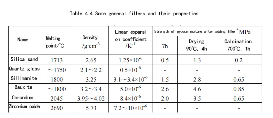
Adding fillers to gypsum can significantly reduce the shrinkage of gypsum molds during high-temperature baking, enhance its crack resistance, and improve thermal conductivity. At the same time, adding 50% of cheap fillers to gypsum can also reduce the cost of gypsum molds.
The filler should have a suitable melting point, refractoriness, good chemical stability, suitable linear expansion rate, small gas evolution and hygroscopicity, etc. Table 4.4 lists several common fillers and their properties.
③ Additives
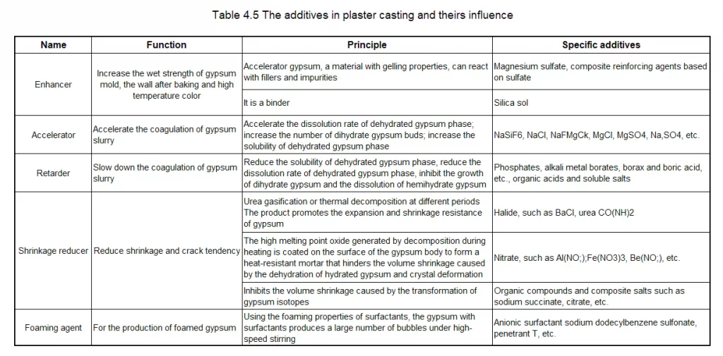
If only fillers are added to the gypsum mold, the residual strength of the gypsum mixture after firing is low, the setting time is not suitable, the gypsum mold has poor disintegration performance during cleaning, the change in linear expansion coefficient is not ideal, and the cracking tendency of large and medium-sized gypsum molds is difficult to eliminate.
Therefore, some inorganic and organic substances must be added to the gypsum mixture to modify the gypsum mixture. We call these added substances additives. Commonly used additives and their functions are shown in Table 4.5.
2.2 Plaster precision casting process
① Preparation of gypsum slurry
For CNC processing prototypes, the gypsum mold precision casting process generally adopts the demoulding method. In the experiment, 55% dihydrate gypsum, 45% quartz sand, and 55% water are used to prepare the gypsum slurry. The specific operation points are as follows:
(1) Weighing: Weigh various materials in proportion;
(2) Adding materials: First add water-soluble additives and glass fiber into water and stir evenly, then add powder while stirring;
(3) After adding powder, immediately close the top cover of the mixing chamber to evacuate the vacuum, and continue stirring. The vacuum degree should reach the specified value of 0.05~0.06MPa within 30s, the stirring time is 2~3min, and the mixer speed is 250~350r/min;
(4) Pouring:The initial setting time of gypsum slurry is generally 5~7.5min. The stirring must be completed before the initial setting before pouring can begin.
➁ Grouting
Vacuum grouting is generally used for small and medium-sized castings, and large castings can only be grouted in the atmosphere. To prevent surface pores when grouting in the atmosphere, a thin layer of slurry should be brushed or sprayed on the surface of the model before grouting. For demolding gypsum grouting, a release agent should be applied to the surface. Commonly used release agents include paraffin or stearic acid kerosene solution, soapy water, vaseline, etc. Vacuum grouting steps:
(1) Preparation:
Place the box frame with the module into the grouting room, and then evacuate to 0.05~0.06MPa;
(2) Grouting:
Inject the slurry into the box frame steadily. The grouting time depends on the size and complexity of the module. When grouting, it should be noted that the slurry should be introduced from the bottom along the edge of the box and then gradually rise. The rising object should not be directly driven into the module:
(3) Mold removal:
After grouting, the vacuum should be broken immediately and the plaster mold should be removed:
(4) Equipment cleaning:
The equipment should be rinsed quickly to prevent residual secondary dihydrate gypsum due to unclean cleaning, which will accelerate the solidification of the slurry when stirring the next batch of slurry:
(5) Standing:
After grouting, the plaster mold must be left standing for 1~1.5h to give it a certain strength. During this period, no vibration or other external loads should be generated, otherwise the strength and precision of the plaster mold will be destroyed, and even the plaster mold will be broken.
③ Roasting
During the firing process, the gypsum mold undergoes a series of phase changes, accompanied by a sharp change in volume. In addition, the thermal conductivity of the gypsum mold is low, so the firing should be carried out in steps, and each section should be kept warm for a certain period of time to make the inner and outer wall temperatures consistent.
For demolding gypsum molds, since there is no residual wax in the mold, only a firing temperature of 250~300℃ is required to remove free water and product water. For melting molds, since the residual wax will penetrate into the gypsum mold during dewaxing and must be burned out, the firing temperature must reach 700℃.
The following are the process parameters for firing ordinary gypsum molds in a drying furnace in the experiment:
100℃, 5h150℃, 5h->250℃, 20hPouring should be carried out in an anhydrous state, and the gypsum mold is no exception.
Therefore, the gypsum mold should be in an anhydrous state after baking. The inspection method adopts the weighing constant weight method, that is, during the drying process, the sample is weighed at different time intervals, and it is completely dry when it reaches a constant weight.
④ Pouring and casting cleaning
After the gypsum mold is completely dry, different pouring processes can be used according to the casting structure and the type of gypsum mold. Gravity pouring is simple to operate, as long as a reasonable pouring system is designed.
The aluminum alloy casting mold to be introduced later was used in the experiment, with a casting temperature of 100~200℃ and a pouring temperature of 700~750℃.
For some large thin-walled precision castings, a lot of detailed cleaning, trimming and correction work must be done after pouring to obtain qualified castings with good quality.
2.3 Common defects of castings and their prevention methods (see Table 4.6)
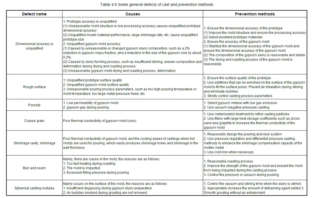
3. Lost Foam Casting Process Based on CNC Machining Prototype
Although plaster casting can produce high-precision molds, since plaster casting is performed on the basis of CNC machining prototypes, it increases the difficulty of process flow and precision control.
Therefore, after the foam plastic model is CNC machined, the lost foam casting method is also used in the experiment to directly manufacture molds that can be used directly or after a small amount of processing.
The test adopts sand casting, the molding sand adopts acid-catalyzed resin self-hardening sand, and the alloy material adopts HT250.
The prototype processed by CNC is placed in the sand box, and the upper and lower boxes are molded with resin sand respectively. After 30 minutes, the resin sand is cured and coated on the sand mold, and then poured. The pouring temperature is about 1460℃. After cooling for 1 hour, open the box, take out the casting, and shot blast clean to remove the sand adhering to the casting.
The products manufactured by this process can be used directly with little or no processing.
After analyzing the above process flow, it can be seen that in order to obtain the final qualified parts products and fully reflect the excellence of the process, the following factors must be considered:
(1) During CAD modeling and mold design, some process characteristics of subsequent processing procedures should be fully considered, including shrinkage allowance, machining allowance, casting process parameters, etc.;
(2) When processing the model, it should be rough-processed with a milling cutter first, and then fine-processed with special tools to achieve the required accuracy. The processed model should be surface treated to obtain a better prototype surface quality;
(3) Paint should be applied before pouring to improve the quality of the casting and reduce surface defects of the casting:
(4) Heat treatment should be performed to make the mold have higher performance.
Research on aluminum-based mold materials for rapid mold manufacturing
1. Development of Aluminum-Based Materials for Rapid Tooling
1.1 Performance requirements of mold materials[27]
The selection of mold materials is mainly to meet the needs of mold production conditions and mold working conditions. Combined with the basic properties of mold materials and related factors, select mold materials that meet mold needs, are economically reasonable, and have advanced technology. For a mold, if only the basic properties of the material are considered, there may be several mold materials that meet the requirements. However, the mold’s service life, the difficulty of the mold manufacturing process, the cost of mold manufacturing, and the mold cost allocated to each workpiece must be comprehensively considered, and a comprehensive evaluation must be conducted to draw a correct conclusion that conforms to reality.
① Basic properties of mold materials
When selecting mold materials, it is necessary to consider that certain basic properties of the mold must be able to adapt to the needs of the mold being manufactured. Generally speaking, the three properties of material wear resistance, toughness, hardness, and red hardness can more comprehensively reflect the comprehensive performance of the mold material.
② Technological properties of mold materials
In the total manufacturing cost of molds, especially small precision and complex molds, the mold material cost often only accounts for 10~20% of the total cost, sometimes even less than 10%; while the costs of machining, heat treatment, surface treatment, assembly, management, etc. account for more than 80%.
The process performance of mold materials has become an important factor affecting mold costs. Improving the process performance of molds can simplify the mold production process, make manufacturing easier, and effectively reduce mold manufacturing costs. The mold process performance generally considers the following points:
(1) Processability: The processability of mold materials includes cold processing properties, such as cutting, grinding, polishing, cold extrusion, etc., and hot processing properties include thermoplasticity and hot processing temperature range.
For the manufacture of plastic products with leather grain, chemical etching process is generally used, which requires the mold material to adapt to this chemical etching process. In order to simplify the production process, casting process is often used at home and abroad to directly produce casting blanks close to the shape of the finished mold. Therefore, this type of material is required to have good casting process performance, such as fluidity, shrinkage, etc.
(2) Quenching temperature and quenching deformation.
(3) Hardenability and Hardening capacity.
(4) Oxidative decarburization sensitivity.
③ Metallurgical quality of mold materials and other considerations
Metallurgical quality mainly includes smelting quality, forging and rolling process, heat treatment and finishing process, etc. In addition to metallurgical quality, the following requirements should also be considered when selecting mold materials:
1) Thermal conductivity: Thermal conductivity is also one of the main performance indicators of mold materials, especially hot work mold materials and plastic mold materials. Materials with good thermal conductivity can quickly conduct the heat generated during processing and the heat transferred from the workpiece, avoid overheating of the mold working surface, and improve the working conditions of the mold.
For some thermoplastic molding molds and some die-casting molds, in order to speed up the production pace, it is hoped that the workpiece can be quickly cooled and demolded to improve production efficiency.
Sometimes some materials with good thermal conductivity are also selected, such as high-strength copper alloys, high-strength aluminum alloys, etc.
2) Material refinement machining and standardization: In order to shorten the mold manufacturing cycle, the mold manufacturing department should choose to use refined machining materials and standardized parts when purchasing mold materials, which can reduce production costs and improve material utilization.
3) Other factors to be considered: In addition to considering the main properties of the material to meet the requirements of the mold use conditions, the selected mold material should also consider its price, versatility, etc.
1.2 Advantages of aluminum-based alloy molds
For a long time in the past, aluminum alloys were not used in injection mold manufacturing in any field. However, with the general improvement of aluminum alloy properties, especially mechanical properties, and the excellent properties of aluminum alloy materials such as light weight, good cutting performance, high thermal conductivity and electrical conductivity, they have been used more and more widely in mold manufacturing, especially plastic molds in recent years.
Using aluminum alloy materials to manufacture molds can achieve good results in shortening mold manufacturing cycles and reducing costs. Aluminum alloy plastic molds produced by foreign specialized manufacturers have a service life of more than 100,000 times, and after chemical treatment of the mold cavity surface, the service life can reach 200,000 to 300,000 times. The main characteristics of aluminum alloy and mold manufacturing [28,29].
(1) The specific gravity of aluminum alloy is only 1/3 of that of steel. Therefore, plastic molds made of aluminum alloy are light, easy to carry, and can open and close molds quickly.
(2) The allowable cutting speed of aluminum alloy materials is 5 times higher than that of steel, which can greatly shorten the mold processing time, extend the service life of machine tools and cutting tools, thereby reducing mold costs and greatly shortening the mold production cycle.
(3) The heat transfer coefficient of aluminum alloy materials is 4 times higher than that of steel. Therefore, using aluminum alloy to make plastic molds can greatly shorten the production cycle of plastic parts, simplify the design of cooling systems, and greatly reduce the deformation of plastic parts caused by uneven heat transfer.
(4) Since the conductivity of aluminum alloy materials is more than 10 times higher than that of steel, electrical discharge machining(EDM) can become an economical processing method for such materials, and the corresponding processing time can be greatly shortened.
(5) Aluminum alloy has a low melting point and is easy to use precision processes such as plaster molds for precision casting, meeting the requirements of rapid molds.
(6) Aluminum alloys can undergo a variety of surface treatment processes, such as micro-arc oxidation(MAO), and can obtain higher mechanical properties after surface treatment.
1.3 Several aluminum alloys commonly used in mold manufacturing [30]
Hoogovens of Germany has developed and produced three aluminum alloy materials (Hokoto1, Weldural and Gianta1) with high strength, good wear resistance, high dimensional stability, no pores and inclusions, and uniform organization.
Among them, Hokotol has the highest strength and the best wear resistance. The base alloy of Hokotol is 7050, and the main alloying elements are Zn6.5%, Cu2%, and Mg2.2%. The hardness of the supply state is 180HB, the yield strength is 532MPa, the tensile strength is 575MPa, and the elongation can reach 7.8%.
The organizational properties of this material are very uniform. Hokoto1 material has good dimensional stability, so it can manufacture molds with complex shapes and high dimensional accuracy requirements. At the same time, this material also has good polishing properties, and it is easy to obtain good surface roughness. Therefore, Hokoto1 material is suitable for manufacturing injection molds and blow molds.
The characteristics of Weldura1 aluminum alloy material are that in addition to high strength, it also has excellent welding performance. The base alloy of this aluminum alloy material is 2219, and the main alloying elements are Cu6.5% and Mn0.3%. The hardness of the supplied state is 130HB, the yield strength is 335MPa, and the tensile strength is 449MPa.
Compared with aluminum materials such as 7075, this material can still better maintain its strength performance when the temperature rises, so it can also be used to make plastic molds.
The performance of Juta aluminum alloy material is very uniform, with excellent welding performance and good corrosion resistance. This material cannot be heat treated. The hardness of the supplied state is 70HB, the yield strength is 153MPa, the tensile strength is 293MPa, and the elongation is 20.5%.
1.4 Effect of alloying elements on aluminum alloy properties and selection of alloying elements
The aluminum-based alloy materials developed are all forged aluminum alloys, and rapid molds are usually completed by casting. Cast aluminum alloys are pure aluminum with other metal or non-metal elements added. They not only maintain the basic properties of pure aluminum, but also have good comprehensive properties due to alloying and heat treatment.
Among the four major series of cast aluminum alloys, Al-Si alloy has excellent casting performance, good fluidity, good air tightness, small shrinkage, small thermal cracking tendency, and good mechanical properties, physical properties, corrosion resistance and medium machining performance after metamorphism and heat treatment.
As a qualified mold material, in addition to having good mechanical properties at room temperature, the main working conditions are in the range of 200~300℃. Therefore, studying the mechanical properties of materials at high temperatures is one of the basic conditions to ensure the quality of mold materials.
At high temperatures, diffusion, recovery and recrystallization will occur in metals and alloys, so the organization of metal materials used at high temperatures will also change.
In addition, long-term exposure of metal materials to high temperature environments will also cause environmental corrosion of metal materials and affect their performance, such as surface oxidation, shedding of surface compounds, surface corrosion of plastic mold materials, absorption of other trace elements leading to performance changes, etc. Among the many alloying elements, Si, Cu, RE, and Zr have a greater impact on the high-temperature performance of cast aluminum alloys.
As the main alloying element, Si can improve the fluidity of the alloy, reduce the tendency of hot cracking, reduce porosity, and improve air tightness. After adding Si, the alloy has good corrosion resistance and medium processing performance, and has medium strength and hardness.
The main function of Cu is to improve the room temperature strength and high temperature strength of the alloy, and can also improve the mechanical processing performance of the alloy, but the casting performance is poor, especially when the mass fraction of Cu is 4%~5%, the hot cracking tendency of the alloy is the largest, and the hot cracking tendency decreases when it exceeds this content. The addition of Zr can reduce the stress corrosion sensitivity of the alloy and can refine the grains of many aluminum alloys.
Adding an appropriate amount of rare earth (RE) can improve the casting performance of the alloy, increase the fluidity of the alloy, and reduce casting shrinkage, pores, segregation and crack tendency.
Therefore, the experiment mainly considers the influence of these four elements on aluminum alloy mold materials.
2. Test methods
2.1 Design of heating furnace
In recent years, although mature high-temperature tensile test methods such as creep and long-term strength have been widely used, high-temperature short-term tensile tests have not completely lost their importance. This is because under the working conditions of the mold, the short-term tensile performance can meet the requirements.
High-temperature short-term tensile tests require heating of the specimens, so the specimens should be tested on a tensile testing machine equipped with a heating furnace and auxiliary equipment such as temperature measurement and temperature control. The test temperature is measured and controlled by a thermocouple tied to the specimen.
In order to determine the deformation of the specimen, an extension rod is usually used to lead the deformation out of the furnace, and then a dial indicator, reflector or differential extensometer is used for measurement. The elongation of the specimen can also be measured through the observation hole on the heating furnace with a test magnifier.
In short-term tensile tests, the main factors affecting the accuracy are load accuracy, specimen temperature control accuracy, extensometer accuracy and strain rate control conditions [31].
At present, tensile testing machines for measuring strength at room temperature are widely used, but tensile testing equipment specifically used to measure high-temperature mechanical properties is still rare or relatively expensive. Therefore, it is necessary to improve the tensile testing machine at room temperature to meet the measurement needs during the test.
At present, the following methods are commonly used to heat the specimen during high-temperature mechanical tests:
(1) using the flame of a gas nozzle;
(2) in a resistance furnace;
(3) in a molten salt or metal bath;
(4) in a heating box filled with a special gas medium;
(5) directly passing current through the specimen.
The heating methods for various types of specimens can basically be divided into two categories:
1) The heated specimen is directly affected by the surrounding air.
2) Use a liquid or gas insulation sleeve to isolate the specimen from the atmosphere.
When the specimen is directly exposed to the atmosphere, the temperature should be kept stable to avoid oxidation of the specimen. Literature shows that when alloy steel specimens are subjected to high-temperature mechanical tests for a short time at temperatures below 800°C, the generation of oxide scale is very slight [32].
Therefore, the second method is used in the test.
In the structure heated by a tubular electric furnace, the temperature at both ends of the furnace is generally lower than that in the middle, resulting in uneven temperature at both ends of the specimen, which will seriously affect the mechanical properties of the metal and also affect the correct test results.
Therefore, in order to obtain accurate test results, the furnace length is generally made much larger than the specimen length (generally 3 to 5 times, and the furnace equilibrium zone length is not less than 1.5 times the specimen length) [33], and the inner diameter is minimized as much as possible, but the deformation measurement device clamped on the specimen cannot contact the furnace wall. Figure 5.1 is a schematic diagram of the designed tubular electric heating furnace.
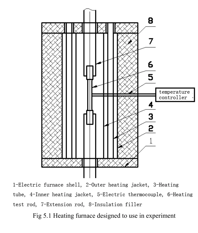
The specimen 6 is fixed to a special extension rod with screws, and the extension rod 7 is clamped on the clamp of the tensile testing machine. To eliminate the possibility of plastic deformation of the extension rod, the ratio of the extension rod to the specimen diameter should not be less than 4. The extension rod must be made of high-temperature, strong, heat-resistant material (such as 3Cr2W8V). The length of the extension rod is determined by the specimen length, furnace height, and working stroke of the testing machine.
The extension rod diameter D of a standard specimen with a diameter of 12 mm is generally 35~40 and the length L is 300~400[41]. The extension rod is connected to the specimen by threads. In order to prevent the extension rod that clamps the specimen from affecting the accuracy of the specimen due to upper and lower center deviations during the measurement process, the extension rod is designed as a universal joint device to achieve automatic adjustment. The specific structural diagram is shown in Figure 5.2. The inner and outer heating sleeves are also made of heat-resistant steel.
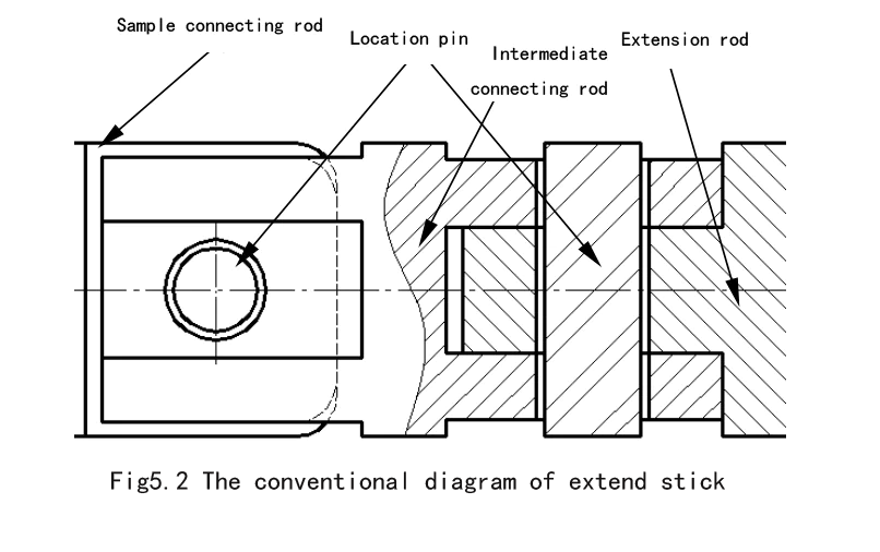
2.2 Experimental materials and methods[34]
The test equipment uses a 20kg capacity resistance furnace and a graphite crucible. The tensile test is carried out according to the GB/T1173-1995 cast aluminum alloy metal mold standard sample. The raw materials used are 99.50% pure aluminum, single crystal silicon, and pure copper, RE and Zr use AIRE10 and A1Zr10 intermediate alloys. In the test, considering that the deterioration will affect the composition of different furnaces, only hexachloroethane is used to refine the alloy melt without deterioration. The specific smelting process is as follows:
(1) Melting with added materials: Add weighed pure aluminum, silicon and Cu into the crucible in turn, set the furnace temperature to 700℃, then turn on the power to heat, stir evenly after complete melting;
(2) Refining: When refining with hexachloroethane, a certain amount of additives TiO₂ or NarSiF6 is usually added to slow down the reaction rate and improve the refining effect. The amount of refining agent added is generally 0.5~0.7% of the total weight of the alloy, the refining temperature is 700~730℃, the refining time is 10~12min, and the slag is removed after standing for 10~15min;
(3) Casting: Heat the mold to 200~250℃, apply paint on the mold cavity, and then gently polish the cavity with fine sandpaper to ensure the smoothness of the cavity. After refining, pour at 580~620℃. After cooling, take out the sample and prepare for stretching in the cast state.
(4) Tensile test: The tensile test is carried out on a WDW3100 microcomputer-controlled electronic universal testing machine produced by the Institute of Testing Instruments, Chinese Academy of Sciences. The tensile test temperature is 250°C, the temperature fluctuation is ±3°C, and the temperature gradient is <3°C: The thermocouple adopts a nickel-chromium-nickel-silicon system, the test temperature is <400°C, and the allowable error is ±3°C: Tie one thermocouple at each end of the calculated length of the smooth specimen, and the working end of the thermocouple should be in close contact with the measuring surface of the specimen. When the temperature reaches the allowable error range, keep it warm for 1 hour and apply stable pressure for the test; each group of tests has no less than 3 valid specimens, and the results are processed by the least squares method and a trend curve is drawn. If one of the following situations occurs, the result is invalid:
a. The sample is cut on the mark or outside the calculated length;
b. There are obvious defects at the mouth;
c. The specimen is overheated, the installation is skewed or the force is abnormal;
3. Sample results and analysis[35]
3.1 Effect of Si on high temperature tensile properties of A1 alloy
As shown in Figures 5.3 and 5.4, in terms of tensile strength, the deformation resistance of the Al-Si (wt7.5%) alloy decreases as the temperature decreases from room temperature to 200°C, and the tensile strength drops sharply after 200°C. As for the reason, the research on the high temperature strength of A356 and 6061 alloy casting alloys in the literature [36,37,38] believes that it is due to dynamic strain aging during the deformation process. The sharp drop in tensile strength above 200°C is considered to be closely related to dynamic recovery and dynamic recombination.
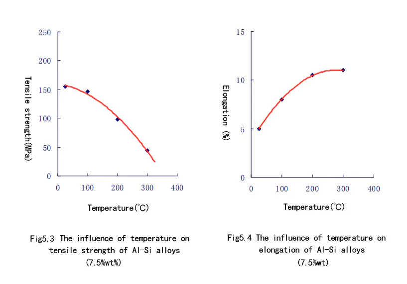
In terms of elongation, as the test temperature increases, the elongation shows an upward trend. Similar to the tensile strength, the elongation increases sharply in the range of room temperature to 200°C, while in the range of 200~300°C, the elongation increases slowly.
3.2 Effect of Cu on High-Temperature Tensile Properties of AlSi7 Alloy
Al-Si-Cu alloy has good casting and cutting performance. It can obtain high mechanical properties without heat treatment and can cast heavy-load and complex-shaped parts. From the ternary isothermal solubility diagram, it can be seen that the existing phases are α (Al), binary eutectic (α+Si) and (α+Al2Cu), and ternary eutectic (α+Si+CuAL2). From the test result Figure 5.5, it can be seen that at 250°C, with the increase of Cu addition, the tensile strength of the alloy also increases linearly, indicating that Cu has a significant effect on improving the high-temperature strength of aluminum alloys.

When the Cu content is high, the alloy is very sensitive to defects, and sudden fracture is likely to occur at the location where the defects exist, and the corrosion resistance decreases with the increase of Cu. A2Cu is the main strengthening phase. After precipitation, the tensile strength and yield point of the alloy are improved, ensuring that the alloy has good cutting performance. It can be seen from the microstructure of Figure 5.6 that the main phases are α(Al) and (α+Al2Cu). As the Cu content increases, the precipitation amount of AL2Cu also increases, thereby improving the tensile strength of the alloy.

3.3 Effect of RE on high temperature tensile properties of AlSi7 alloy
Adding an appropriate amount of rare earth to aluminum alloys can refine the spacing between secondary branches, improve the casting properties of the alloy, increase the fluidity of the alloy, and reduce casting shrinkage, pores, segregation and cracking tendencies, etc. This has been confirmed by many experiments. In the casting of Al-Si binary alloys, adding an appropriate amount of rare earth can also form Al-Si-Ce and Al-Si-Ce-Fe multi-compounds, thereby turning coarse needle-shaped iron into short strips or block-shaped multi-compounds, reducing the harm of needle-shaped iron to the matrix.
As can be seen from Figure 5.6, at room temperature, with the increase of rare earth content, the change in the tensile strength of the AlSi7RE alloy is not very obvious. When the RE content is in the range of 0~2%, the tensile strength value hardly increases, and there is a slight downward trend when the RE content is 0~1%; but when RE exceeds 1.0%, the tensile strength value shows a slow growth trend.
At 250℃, when the RE content is in the range of 0~1%, the tensile strength of the alloy hardly changes: when the RE content exceeds 1.0%, the tensile strength of the alloy shows an increasing trend, but at the value of 1.5%, its tensile strength value is still slightly greater than the tensile strength value when the RE content is 2%.
This is somewhat similar to the conclusions in the literature [39,40,41,42] about the effect of mixed rare earth on the high temperature strength of ZL108 alloy at 300℃. From the elongation curve in Figure 5.7, it can be seen that the effect of RE on the room temperature elongation and the effect of RE on the elongation at 250℃ show completely different trends.
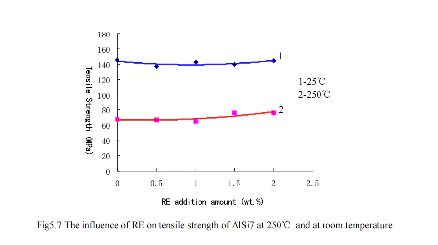

At room temperature, with the increase of rare earth elements, the elongation of aluminum alloy gradually decreases; but at 250℃, with the increase of rare earth elements, the elongation of the alloy increases, and the increasing trend is slower than the decreasing trend at room temperature.
Rare earth elements will produce aluminum-rich rare earth phases in aluminum. Their production temperature (or melting point) is much higher than the melting point of aluminum. Therefore, when rare earths are added to aluminum and the rare earth content exceeds the solubility in aluminum (different rare earth elements have different solubilities in aluminum, La is 0.05 and Sc is 0.22 at 640°C: La is 0.01 and Y is 0.13 at 600°C), an aluminum-rich rare earth phase will be produced and form a co-product with aluminum.
If these common microstructures form skeletons at the grain boundaries under cast conditions, since these phases have much higher strength than aluminum at high temperatures, their presence can prevent grain growth and grain boundary sliding at high temperatures, play a role in grain boundary strengthening, and thus improve the high temperature strength of aluminum and aluminum alloys.
The microstructure in Figure 5.9 also shows that when the RE content is 1.0, the aluminum-rich rare earth phase is relatively less than other components, which is consistent with the strength curve.

However, studies have shown that [43], in most aluminum alloys, the rare earth content that best affects the room temperature mechanical properties of the alloy is generally in the range of 0.1%~0.4%. Because when the RE addition amount is 0.1wt.%, the strength can be increased by ~10%, and further increasing the rare earth content has little effect on the strength and no significant effect on the elongation.
3.4 Effect of Zr on High-Temperature Tensile Properties of AlSi7 Alloy
From the tensile strength curve in Figure 5.8, it can be seen that with the increase of Zr addition, the same change trend is shown at room temperature and 250℃. At room temperature, within the range of Z content of 0~0.2%, the tensile strength of the alloy hardly changes: but when the Zr addition exceeds 0.2%, the tensile strength of the alloy shows a slight downward trend.
At 250℃, the effect is similar to that at room temperature. When the Zr content is in the range of 0~0.2%, the tensile strength of the alloy shows a slight increasing trend. When Z exceeds 0.2%, the tensile strength of the alloy also shows a decreasing trend.
It can be seen from the elongation curve in Figure 5.9 that due to the different curvatures of the room temperature and 250℃ elongations, the two elongation curves intersect at ~0.17%. When the Z content is lower than 0.17%, the room temperature elongation is higher than the 250℃ elongation, but after the Z content exceeds 0.17%, the room temperature elongation drops rapidly and is much lower than the 250℃ elongation. At room temperature, with the addition of Z, the elongation of the alloy drops rapidly, from ~16% when the Z content is 0.1% to ~11% when the Zr content is 0.25%. And from the test results, the addition of Zr causes fluctuations in the room temperature elongation change.

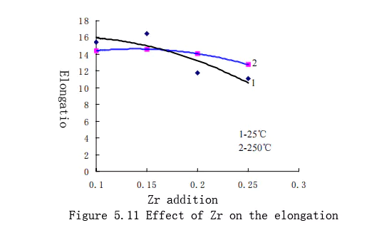
At 250℃, as the amount of Zr added increases, the elongation of the alloy increases slowly, but when the amount of Zr added exceeds the intersection of the two curves ~0.17%, the curvature of the elongation decrease intensifies. Figure 5.12 shows the microstructure of different Zr contents.
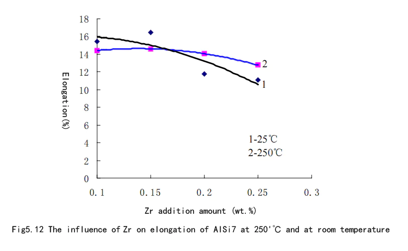
Characteristics of rapid prototyping process based on CNC prototype
Rapid mold manufacturing technology based on CNC machining prototypes integrates CNC machining technology with precision casting molding technology, and has the characteristics of high CNC machining production efficiency, high machining accuracy, easy design changes, flexible machining technology, etc. At the same time, this process is a rapid mold manufacturing technology, so it also has the characteristics of short manufacturing cycle, low cost, diverse methods, and wide adaptability.
In this process, from the design of the 3D CAD model, the preparation of the prototype material to the finishing and debugging of the mold, if the whole process is implemented in parallel and the various processes are effectively coordinated, the mold manufacturing cycle can be greatly shortened, the manufacturing cost can be reduced, and it can be widely used in actual production.
Table 6.1 and Table 6.2 respectively list the cost and duration comparison of traditional machining mold making, laser rapid prototyping and rapid mold manufacturing process based on CNC machining prototype [44].


① Cost analysis
As can be seen from Table 6.1, although the rapid mold processing technology based on CNC machining prototypes increases the prototype material cost and prototype CNC machining cost, the final mold only needs a small amount of CNC machining or no CNC machining to obtain a mold cavity with complex curved surfaces, which greatly reduces the processing cost of using CNC machining to process complex mold cavities, thereby reducing the overall mold cost by about 30%. Secondly, if the prototype material is mass-produced and with the large-scale application of this process, its cost will be further reduced.
② Process time analysis
From the perspective of process time, the rapid mold manufacturing process based on CNC processing prototypes increases the preparation time of prototype materials and the CNC processing time of prototypes. However, since the processing time of foam plastics is greatly reduced compared to the processing of ordinary metals, the final mold only needs a small amount of CNC processing or no CNC processing to obtain the final mold, thus shortening the overall mold manufacturing cycle.
In summary, the rapid mold manufacturing process based on CNC machining prototypes can achieve precision control and error compensation of the entire manufacturing system under the CAD environment; it can be combined with various forms of rapid precision molding technology, and adopt processes of different complexity and cost according to different requirements to better control the precision, surface quality, mechanical properties and service life of the mold. It can effectively realize parallel manufacturing of various links, which has great advantages in reducing mold manufacturing costs and shortening production cycles, and has obvious direct economic benefits.
Conclusion and Outlook
1. Conclusion
In this project, we firstly control the accuracy and compensate the errors of the part models in the CAD system environment, and then use the CNC processing equipment to quickly process the wax mold, foam plastic mold or machinable polymer material mold for precision molding, and make the metal mold finished or semi-finished product from the mold material studied. Through the experimental comparison, we can get the following conclusions:
(1) The rapid mold manufacturing process based on CNC machining prototypes combines the advantages of CNC machining technology and precision molding technology. Compared with pure CNC machining, this process saves the expensive CNC machining costs and will have great advantages in the processing of complex-shaped, refractory and difficult-to-process metal parts and mold manufacturing. Compared with the current laser rapid prototyping technology, it can save the cost of purchasing expensive rapid prototyping machines, saving costs for enterprises and can be widely used in actual production.
(2) In the experiment, polystyrene foam was used as the prototype material for CNC machining, but its production process must be optimized. The higher the density of the foam, the better the processing performance, but due to the increase in density, the foaming process must be optimized to obtain better quality.
(3) The surface finish of foam plastic during milling depends largely on the structure of the milling cutter, the sharpness of the blade and the cutting process parameters. When milling a plane, the spindle speed is generally around 3000rpm. When processing fillets and inner circles, 4200rpm is appropriate. After milling foam plastic, surface treatment is required to obtain the best surface quality.
(4) For aluminum alloy mold materials, as the temperature increases, the tensile strength of the A1Si7 alloy decreases and the elongation increases. At 250°C, as the Cu addition increases, the high-temperature strength of the alloy also increases, the corrosion resistance of the alloy decreases, and the sensitivity to defects increases. RE and Zr have limited effects on the high-temperature strength of the alloy. As the element addition increases, the high-temperature strength of the AISi7RE alloy increases slowly, while the elongation at room temperature and 250°C shows the opposite trend. The high-temperature strength of the A1Si7Zr alloy begins to increase, but when the Z content exceeds 0.2%, the tensile strength of the A1SiZr alloy decreases, and the elongation of the alloy decreases faster at room temperature than at high temperature.
(5) The rapid prototyping manufacturing process based on CNC machining prototypes uses CNC machining technology. This inherently determines that it has both the disadvantages of CNC machining technology, that is, it cannot complete the direct manufacturing of complex internal flow channels; and the disadvantages of indirect rapid prototyping technology, that is, it will lose accuracy during multiple prototype conversions. This needs to be gradually resolved in the future development process.
2. Prospects for follow-up research
From the above conclusions, it can be seen that the characteristics of rapid tooling determine that its basic application range can only be simple, economical, and rapid mold manufacturing or for the development of new products. As a new type of rapid mold manufacturing process, the rapid mold manufacturing process based on CNC machining prototypes has the typical characteristics of rapid molds. Therefore, the following aspects must be improved in future development:
1) Since the indirect method is difficult to control precision, the key to improving the indirect method manufacturing precision is to develop a short-process rapid manufacturing process, reduce precision loss, and stabilize the working environment. Therefore, using paraffin with higher CNC machining precision to replace foam plastic as the prototype material is one of the development directions of this process;
2) The basic characteristics of rapid tooling are low cost and short cycle. As a good prototype material, foam plastics are constantly optimizing their processes and developing high-density foam plastics suitable for CNC machining, which is an effective way to improve process size and surface accuracy, material adaptability and practicality;
3) Aluminum alloy mold material is one of the hot spots in the current research of rapid mold materials. Continuing to develop aluminum alloy materials with better mechanical properties suitable for plastic mold manufacturing will have great advantages in reducing mold manufacturing costs and shortening mold cycles.
References:
- [1] Center for Laser Rapid Forming, Department of Mechanical Engineering, Tsinghua University, Beijing, PR China.
- [2] Idisas, SuzukiT, Fundamental study of metal infitration in selective laser sintering. InProceeding on the 8th Intem Conf On Rapid Prototyping, Tokyo, Japan, June12-13.2000.401-406:
- [3] Prinz F B, Wiss L E. Novel Applications and Implementations of Shape DepositionManufacturing. Progess in Rapid Prototyping Manufacturing an Rapid Tooling. Proceedingon the 1st intern Conf on Rapid Prototyping & Manufacturing’98, Beijing, China, July21-23,1998.20-29:
- [4] Song Y-A, Park S. Feasibility study of using 3D welding and milling process for rapid tooling. InProceedings on the 8th Intern Conf on Rapid Prototyping. Tokyo, Japan, June 12-13, 2000438-443:
- [5] Yan Yongnian et al., The latest progress and development trend of rapid tooling technology, Aviation Manufacturing Technology, 2002(4), p17-21;
- [6] Zhao Guangqing et al., Modern rapid and economical mold manufacturing technology, Mold Industry, 2000 (3), p3-7;
- [7] Wang Jianye, Xu Jiawen, Principles and Applications of Electrochemical Machining, Beijing: National Defense Industry Press, 2001;
- [8] Rajurkar K R, Zhu D, McGeough J A, etal. New development of elecrtrchemical machining.Annals of CIRP1999,48(2):567-579:
- [9] Li Fazhi, Advanced Mould Manufacturing Technology, Machinery Industry Press, Beijing, 1st edition, April 2003;
- [10] Li Cuiyu et al., Rapid tooling technology based on rapid prototyping, Journal of Hebei University of Technology, 2002(12), Vo1(3)No.6, p53-57;
- [11] Zhang Haiou et al., Current status and development trend of rapid mold manufacturing technology, Mold Technology, 2000, No.6, p84-89:
- [12] Nakagawa T. Rapid prototyping in Japan. In Proceedings on the 8" Intem Conf on RapidPrototyping,Tokyo.Japan.2000.P1-16:
- [13] Zhang Haiou, Wang G L, nakagawa 'T, Rapid hard tooling by Powder spray of stainless steel. InProceedings on the 8* Intern Conf on Rapid Prototyping, Tokyo, Japan, June 12-13, 2000p444-449:
- [14] Chen Yanxiang, Wang G L, Zhang H O, Computer simulation of coating deposition processin rapid spray tooling. In Proceedings on the 8" Intern Conf on Rapid Prototyping, Tokyo.Japan, June 12-13,2000,p450-455;
- [15] Zhang Renji, Yan Yongnian, et al., Electroforming mold manufacturing based on laser rapid prototyping technology, Proceedings of the Fourth National Laser Processing Academic Conference, Beijing: Metallurgical Industry Press, 1997, p1-7;
- [16] Wang Guangchun et al., Rapid prototyping and rapid mold manufacturing technology, New Technology and New Process, 2000(9), No. 6, p30-32;
- [17] Xu Hefeng et al., Digital Mold Manufacturing Technology, Chemical Industry Press, Beijing, 1st edition, June 2001;
- [18] Liang Guangze et al., Full-Mold Casting (3rd edition), Shanghai Science and Technology Press, 1st edition, December 1990
- [19] Li Fazhi, Advanced Mold Manufacturing Technology, Machinery Industry Press (Beijing), 1st edition, April 2003;
- [20] Casting Mold Manual Editorial Group, Processing and Forming of Polystyrene Foam Plastics Molds, Casting Mold Manual, Machinery Industry Press, 1987, p995~1015;
- [21] Liang Guangze, Research and Application of Foam Plastic Molds for Full Casting, Shanghai Mechanical Manufacturing Technology Research Institute, 1979;
- [22] Shanghai Mechanical Manufacturing Technology Research Institute, Shanghai Heavy Machinery Plant, Processing of Foam Plastics, Foundry, 1972(7);
- [23] Liang Guangze and Yu Caiming, Research on Air-cooled Surface Milling Cutter, Shanghai Mechanical Technology Research Institute and Guangzhou Heavy Machinery Factory, "Selected Technical Materials of Full-mold Casting", Shanghai Science and Technology Literature Publishing House, 1978, p.8~10;
- [24] Luo Yunhua et al., Three-dimensional modeling and CNC machining of vaporization molds, Mold Technology, 2000, NO(4), p83-85;
- [25] Gao Yixi et al., Plaster Mold Investment Casting Technology and Theory, Northwestern Polytechnical University Press, first edition in August 1992;
- [26] Foundry Branch of the Chinese Mechanical Engineering Society, Casting Handbook (Special Casting), Machinery Industry Press (Beijing), 2nd edition, February 2003:
- [27] Xu Jin, Chen Zaizhi, et al., Handbook of Mold Material Application, Machinery Industry Press, 1st edition, 2001.
- [28] Germany Georg Menges, Walter Michaeli, Paul Mohren et al., Chemical Industry Press, January 2003 First Edition.
- [29] Computer in Industry,1999.39(3):3~10; Detlef Kochan, chua Choe Kai, Du Zhaohui, Rapid prototyping issues in the 21* centery
- [30] Li Zhigang et al., Rapid tooling technology and aluminum alloy materials for rapid tooling, Die & Mold Industry, 2000(9), p9-11;
- [31] Yang Yike et al., High Temperature Strength and Test of Metals, Shanghai Science and Technology Press (Shanghai), first edition in June 1986;
- [32] High Temperature Mechanical Properties of Metals, by A.M. Boltz Descartes, translated by Meng Fanjie, Metallurgical Industry Press, 2nd edition, September 1957;
- [33] The Science and Technology and Quality Supervision Bureau of the Ministry of Machinery Industry compiled the Mechanical Engineering Materials Testing Manual (Mechanics Volume), Liaoning Science and Technology Press, 1st edition, December 2001:
- [34] Zhu Huadong, editor-in-chief, Latest Practical Handbook of Casting Standards, Ordnance Industry Press, first edition in November 1992:
- [35] Lu Wenhua et al., Casting Alloys and Their Melting, Machinery Industry Press, 2nd edition, 1996:
- [36] China Foundry Association, Collection of Taiwan Foundry Papers, China Foundry Association, 1989;
- [37] Hong Hongci et al., Proceedings of the 1976 Foundry Papers of the Taiwan Foundry Society, 1987, 22/1~22:
- [38] Cai Zhaofeng, Master's thesis, Institute of Mining, Metallurgy and Materials, National Cheng Kung University, 1988;
- [39] Cai Huimin, Application of mixed rare earth in A1-Si alloy, Special Casting and Nonferrous Alloys, Issue 6, 2001, p9-11;
- [40] Granger Aluminium alloys for Elevated Temperature application. AFS Trans. 1986.94:777-782:
- [41] Sharan R. Rare additions as Modifiers of Aluminium Silicon Alloys.AFS International CastMMetals Journal, 1978.3(1):29-33:
- [42] Ye B An assessment of theRole Earth in the Eutectic Modification of Cast Aluminium-Sillicon Alloys,AFS Trans,1985.93:533-544:
- [43] Sun Weicheng et al., Behavior of Rare Earth in Aluminum Alloys, Ordnance Industry Press, 1st edition, March 1992;
- [44] Cao Hanxue, Rapid Tool Manufacturing Based on Rapid Prototyping Technology and Concurrent Engineering, Master's Thesis of Chongqing University in 2003
https://www.ruiyi-cncmachining.com/rapid-tooling-technology-based-on-cnc-machining-rapid-prototype/ by RuiYi is licensed under CC BY-NC 4.0
