
Titanium alloy is a very important non-ferrous metal. It has high specific strength, low density, good high-temperature deformation performance, and excellent corrosion resistance.
These advantages make it widely used in various fields such as aviation, aerospace, industry, national defense, and medicine.
The complicated titanium alloy parts made by traditional casting and forging methods are seriously affected by low material utilization and high costs.
The process is also complicated, and there is a high difficulty in subsequent mechanical processing.
These factors severely affect the wide application of titanium alloy parts.
3D printing technology is very different from traditional industrial processing methods.
It has a very high material utilization rate, offering significant advantages over traditional molding processing methods.
This technology allows for a close combination of initial design, process verification, and production.
It can quickly enable small-scale product innovation and shorten research and development time.
In recent years, the unit has seen an increasing number of scientific research and new trial production tasks.
The existing manufacturing technology is becoming increasingly difficult to meet the required cycle time and quality standards.
In this paper, we will take titanium alloy thin-walled cylinder shell parts as an example, 3D printing molding and subsequent machining applications to explore.
Parts process analysis
Structural characteristics
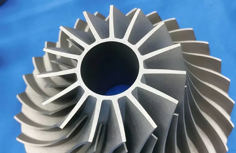
The shell is an important component of aviation aircraft life-saving products. Its three-dimensional model is shown in Figure 1.
The material used for the part is titanium alloy.
The main structure consists of a thin-walled cylinder. The wall plate, screw, and air intake connection device form a cantilevered structure.
The inner cylinder, screw, wall plate, and air intake holes have high precision assembly requirements.
However, the remaining cylindrical surfaces do not have the same level of precision.

Material analysis
The material grade of the shell parts is Ti6AlV4, which is characterized by low density, high melting point, high strength, low thermal conductivity, etc.
It also has good mechanical properties and corrosion resistance, and is widely used in aerospace and automobile manufacturing.
Its detailed parameters are shown in Table 1.

Process design
Process difficulties
The parts have high precision requirements and are complex shaped parts with curved frame.
Support structure, the lack of support in the normal direction of the surface of the part will produce large deformation, and strong support is needed to control the deformation;
The strength of the product is required to be high, and it is not easy to control the deformation.
The outer surface of the part is no longer machined, need to control the growth direction through reasonable placement and support to control the deformation.
Equipment selection
According to the process requirements, the 3D printing powder is titanium powder Ti6Al4V.
The equipment mainly consists of several key modules. These include the laser, scanning galvanometer, control system, and monitoring system.
It also includes the powder spreading and powder supply systems.
Three-dimensional model design
Due to the high machining precision of 3D printing equipment, the outer shape of the printed workpiece is highly accurate.
Therefore, it should be produced without additional machining allowance whenever possible.
However, for areas with fitting requirements or those that exceed the machining precision of the equipment, a 2 mm allowance can be reserved.
Additionally, depending on the subsequent machining process, a clamping method such as a collet may need to be added.
According to the equipment’s processing capacity and the size of the parts, a multi-piece layout can be used, as shown in Figure 2.
This approach can significantly improve the production efficiency of 3D printing.

According to the main characteristics of the parts, the products belong to a cylindrical thin-walled structure.
When determining the print placement, it is necessary to consider the overall dimensional consistency of the cylindrical structure and its deformation trends.
Additionally, the powder melting characteristics of each printed layer should be taken into account.
Based on these factors, placing the parts vertically is a more scientific and reasonable choice.
After determining the placement angle of the part, it is important to reduce deformation caused by gravity-induced fluid flow during the printing process.
To achieve this, a support structure should be added under cantilevered features.
It is recommended to orient the beveled end downward to help minimize the amount of support material used. The support plan is illustrated in Figure 3.

Print process control
Check the substrate
Before starting the printing process, it is necessary to confirm that the laser printing area and layout are consistent.
The surface of the printing substrate should be free of slag, oxides, oil, and other contaminants.
If there is rust on the surface, it can be removed by sanding with sandpaper.
The substrate serves as the reference base for the printed workpiece and also acts as the attachment carrier.
The material of the substrate should be consistent with that of the workpiece.
Its surface flatness should be ≤ 0.03 mm, and the surface roughness should be ≤ Ra 0.8. Overall flatness should also be maintained within 0.03 mm.
Add powder
Titanium alloy powder should be checked before adding to ensure that there is no pollution, no lumps, no color change.
Before adding the powder, it should be heated in an oven at a temperature of 80 °C ± 15 °C for no less than 1 hour.
After heating, the powder should be sieved using the specified mesh density to ensure proper fluidity before adding it to the equipment.
The volume of powder added should be more than twice the volume of the printed workpiece.
This helps avoid the need to open the bin to add powder during the printing process, which could cause the equipment to suspend operation.
Environmental confirmation
Before printing the device, the need for its operating environment, hardware conditions and so on to confirm.
1. The equipment’s industrial computer hard disk should have enough storage space to prevent data loss caused by insufficient storage during the processing.
2, The inert gas source should be sufficient, with argon purity of ≥ 99.99%.
This ensures that the oxygen content in the construction environment remains stable during the processing..
3, The equipment should be placed in an environment where the ambient temperature is maintained between 15-30°C.
Additionally, the humidity should be kept below 50% to prevent moisture from affecting the powder and to avoid damage to the device.
4. Check whether the water circuit, electric circuit, anti-static device is normal.
3D printing process parameter settings
First, the workpiece’s “.slc” format solid slice file is imported into the filling software.
Next, its filling parameters are set, including laser power, speed, scanning spacing, scanning mode, fill line cycle angle, contour spacing, fill offset, and other relevant information, as shown in Table 2.
Finally, the “.epi” format file is generated and imported into the printing device.

Before starting the printing process, the material cylinder should first be raised by 0.3mm.
This helps prevent the first layer of powder from being insufficient due to settling in the cylinder.
Next, the number of times the initial powder supply is applied can be appropriately increased to ensure the powder amount is sufficient.
To ensure optimal powder utilization, after processing 20 layers, the number of times the powder is laid can be gradually reduced.
Each adjustment should be made in multiples and followed by observing the powder laying situation after every two applications.
Finally, after pressing the “Start Printing” button, the system will automatically prepare the processing environment.
The printing will begin once the processing conditions meet the required standards.
Finally, press the “Start Printing” button. After this, the system will automatically prepare the processing environment.
The printing will begin automatically once the processing conditions reach the required standards.
Clean up the workpiece
After the workpiece printing is completed, the molding cylinder is slowly raised.
The powder on the substrate is then swept to the recycling bottle under the discharge port using a brush.
The substrate is unloaded and cleaned with an explosion-proof vacuum cleaner to remove any floating powder on the surface of the workpiece and the substrate.
This cleaning process ensures that the workpiece and substrate are ready for appearance inspection and subsequent heat treatment.
Note that: the operator must wear a good dust mask, rubber gloves and protective clothing, timely use of explosion-proof vacuum cleaner to suck away the dust.
Inspection of the workpiece
Check the appearance of the workpiece form and its consistency with the design model. Ensure there is no adhesion between the workpiece and other parts.
The combination of the workpiece, specimen, and substrate should be normal, with no cracks present.
Any cracks in the workpiece or specimen should not be visible to the naked eye.
The appearance of the workpiece should have a consistent color, with no bumps, scratches, bruises, or other defects.
Additionally, there should be no residual powder on the workpiece.
3D printing post-processing
3D printing workpiece post-processing procedures mainly include heat treatment, de-support, special inspection, sand blowing and subsequent processing.
According to research data on the titanium alloy deposition state, the residual stress of the printed workpiece can be significantly reduced after annealing heat treatment.
This is related to the heat treatment of residual stress in the material. Additionally, the residual stress becomes uniformly distributed.
If the metal powder is not dry enough or absorbs air impurities, argon bubbles may form during the printing process.
These bubbles can lead to internal pores in the workpiece, resulting in a small spherical shape. After hot isostatic pressure treatment, the internal pores will be reduced.
However, the impact on the mechanical properties of the material is not significant.
Heat treatment
After checking the appearance of the workpiece, generally should be de-stressed within 24h heat treatment.
In the actual heat treatment process, an electric heating furnace is selected for heat treatment. The heat treatment is performed with the substrate together.
To control temperature accuracy, a thermocouple can be placed in the heat treatment process load.
This ensures the uniformity and consistency of the temperature.
The thermocouple is used to monitor the actual temperature of the workpiece. The specific parameters are shown in Figure 4.

De-supporting
After heat treatment of the workpiece, the base plate can be cut off by wire-cutting equipment, and then the auxiliary support frame can be removed by pliers.
Since most of the support structure is composed of thin-walled or trussed thin strips, pliers and other tools can be used to remove.
Connections such as burrs and other residues, you can wind gun, sandpaper and other tools for trimming and sanding and polishing.
Special inspection
At the same time the need for the strength and chemical composition of the blank through the test piece inspection, to ensure that the strength and material composition qualified.
Sandblasting
After 3D printing, the surface roughness of the parts is not uniform. Additionally, there is an oxide film formed after heat treatment, and oil residue remains after wire cutting.
To address these issues, the sandblasting process is chosen to improve the surface roughness of the workpiece.
This process helps achieve a uniform and consistent metal color on the surface, enhancing the appearance of the workpiece.
Machining
According to the machining art program for processing the bore, a homemade three-jaw chuck is used to clamp the entire outer circle.
The rough and fine boring of the bore is performed from one end.
Due to the larger depth and the elongated overhang of the boring tool, the process generates vibration.
This vibration leads to poor surface roughness at the end of the bore.
Additionally, after removing the workpiece, the bore experiences superimposed deformation.
In the rough and finish machining of the mandrel tooling shape, the clamping can locate and correct the workpiece.
However, after machining, removing the workpiece causes deformation because the bore is not supported.
Another solution is to remove the 3D-printed thickened clamping.
In addition, the removal of 3D printing thickening collet will also produce stress release, resulting in deformation of the workpiece.
To solve the problem of workpiece scrap caused by exceeding multiple dimensions during machining, the following measures have been developed.
1. Bore Turning Optimization: Separate Passes to Prevent Deformation
Turning bore roughing and finishing separately, adjust the margin allocation, to eliminate deformation.
Bore reserve 1mm margin, processing to size ¢ 81H8, as the mandrel positioning reference.
2. Use Expansion Mandrel to Eliminate Clamping Force Effects
Design turning expansion mandrel instead of three-jaw chuck clamping to eliminate the effect of clamping force.
Work step 1 to seal the groove end of the bore as a reference using the expansion mandrel positioning clamping, machining M84 × 1 internal threads and ¢ 82H8 bore.
Step 2: Position the ¢82H8 bore as the reference and clamp it with M84×1 female thread to machine the right end bore and sealing groove.

3. Optimize Milling Path and Sequence to Minimize Re-Clamping Deformation
Adjust the fine-turned bore to the back of the digital milling profile to eliminate deformation caused by re-clamping and machining.
Change the digital milling path by predicting the deformation.
Additionally, adjust the machining strategy of the cutting layer from depth-prioritized to depth-prioritized to further reduce deformation.
4. Use Shock-Absorbing Toolholder and Optimized Geometry to Reduce Vibration
Using a ¢32 internal cooling shock-absorbing toolholder, along with a turning tool tip radius of 0.4, effectively eliminates vibration during the machining process.
Additionally, with a tool front angle of 5° and a back angle of 15°, tool life is significantly improved.
5. Optimize Cutting Parameters to Avoid Vibration Zones
through the optimization of cutting parameters, adjust the cutting line speed, active avoidance of vibration zone.
Using a lower linear speed combined with a large depth of cut and small width of cut, or alternatively, a large depth and width of cut, results in effective chip formation.
Under these machining parameters, the material removal rate is high.
6. Optimize 3D Printing Allowance for Uniform Stress Distribution
Optimize the 3D printing blank allowance, so that the allowance is uniformly distributed to reduce the internal stress generated.
Conclusion
Through the application of 3D printing technology in the manufacturing of titanium alloy thin-walled parts, valuable practical experience has been gained.
This experience, based on the additive manufacturing process, provides a reference method for the subsequent processing of similar parts.
3D printing manufacturing features a short production cycle, high precision, and the ability to produce parts in a near-net shape.
These characteristics free new product design from the limitations of traditional manufacturing processes.
This enables the integration of product structure and function, achieving lightweight, compact, and multifunctional designs.
As a result, it supports rapid updates and iterations, ultimately reducing the cost of scientific research.

