
Ultra-thin-walled metal component machining serves as a key indicator of precision manufacturing capability.
While current internationally leading roll forming processes can produce “tearable steel” sheets as thin as 0.03mm, they face limitations such as limited processing versatility and high equipment dependency.
This paper focuses on the turning of 0.018 mm thick aluminum alloy cylindrical components.
The technical challenges include: achieving wall thickness tolerances at IT2 to IT3 precision levels; controlling cylindricity over an 80 mm machining length; and mitigating thin-wall tearing risks caused by micro-Newton-level cutting forces.
Existing literature lacks reports of thin-wall turning processes exceeding the 0.018 mm critical threshold.
Through innovative fixture design and optimized cutting parameters, this study achieves stable machining of 0.018 mm wall thickness aluminum alloy parts for the first time, offering new insights for manufacturing complex ultra-thin components.
Characteristics
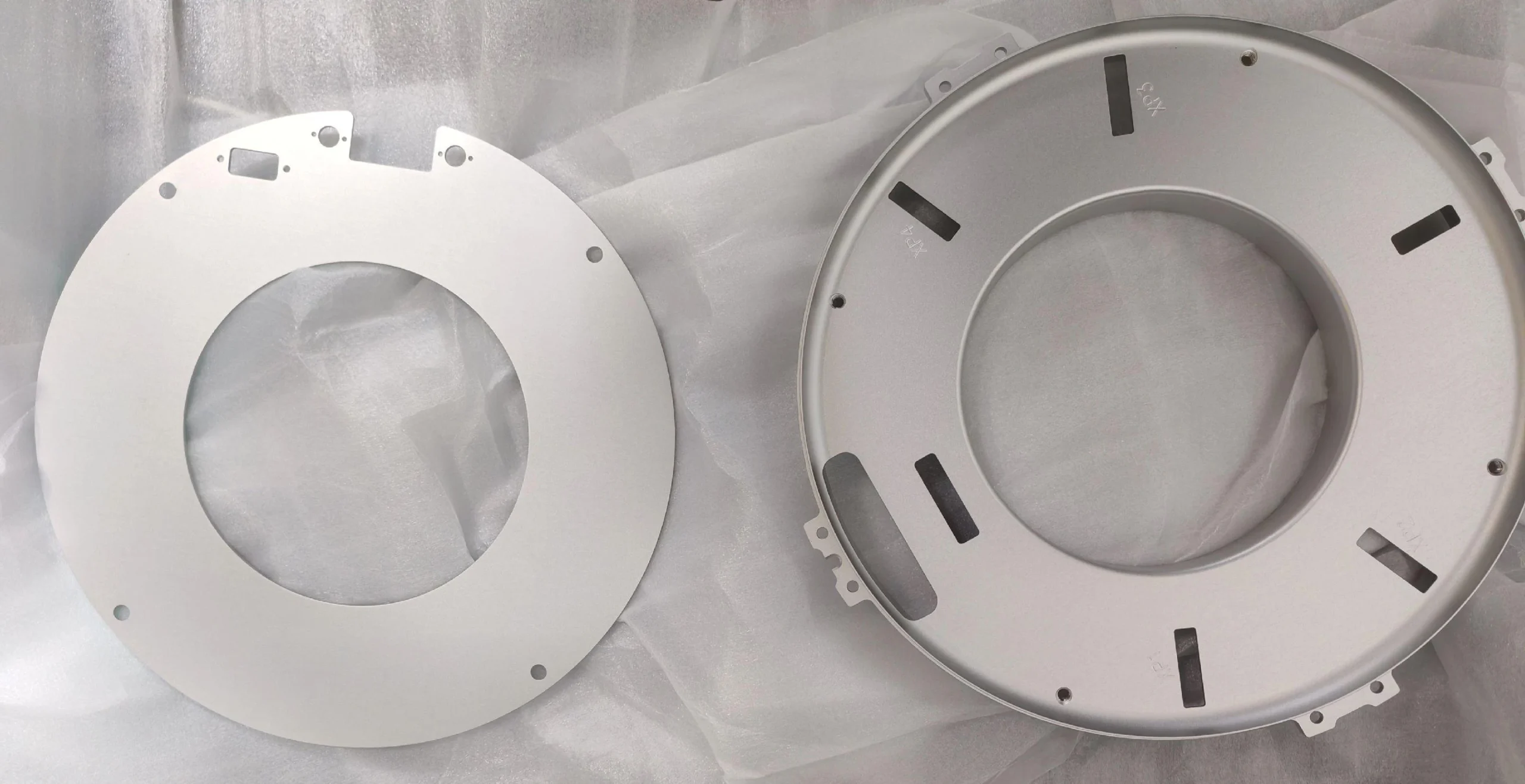
The turning process for 0.018mm ultra-thin wall components (see Figure 1) represents an extremely challenging and high-precision machining operation.
To date, no publicly documented cases of thin-wall turning below 0.018mm thickness exist either domestically or internationally.
This case exemplifies the cutting edge of advanced manufacturing technology.
Internationally, hand-tearable steel currently ranges from 0.03 to 0.04mm thick, while domestically it measures 0.015 to 0.03mm.
However, manufacturers produce hand-tearable steel via roll forming, a process limited to sheet materials.
In contrast, our approach uses CNC turning, providing greater flexibility.
Machining parts with a 0.018mm wall thickness demands high standards in equipment precision, process control, materials, fixtures, cutting tools, and operator skills.
This paper provides a detailed analysis of the machining process for 0.018mm wall thickness parts, addressing each of these critical aspects.

Machining Precision Analysis and Machine Tool Selection
0.018mm represents the IT6 precision grade (0.009–0.0185mm) in mechanical machining, corresponding to the tolerance level for CNC turning events in national and international competitions.
An ultra-thin wall thickness of 0.018mm demands machining precision controlled at an extremely high level, with tolerances within 0.005mm or even smaller.
Additionally, with a machining length exceeding 80mm, stringent requirements for part coaxiality, straightness, and other parameters further increase processing difficulty.
This far exceeds the precision scope of ordinary machining, falling within the micrometer-level machining accuracy category.
For machining with a base dimension of 0.018mm wall thickness, conventional lathes cannot meet the required precision.
Taking the Shenyang CA6140 conventional lathe as an example, its longitudinal feed accuracy typically ranges between 0.028mm and 0.054mm, making the task unfeasible.
Operators must select a CNC lathe that offers superior rigidity, stability, spindle accuracy, and precise X/Z-axis positioning and repeatability for the job.
Table 1 presents a comparison of key precision parameters for various machine tools.
Considering machine tool precision and stability, engineers ultimately selected a turning-milling composite machining center to complete the machining.

Process Innovation and Optimization
Design of an Expansion-Adsorption Clamping System
1.Challenges in Clamping Ultra-Thin-Walled Components
Ultra-thin-walled components are highly susceptible to deformation during clamping.
Conventional clamping methods often cause distortion due to uneven or excessive clamping force, compromising subsequent machining accuracy.
However, for components with wall thicknesses as thin as 0.018mm, any form of clamping force will induce deformation.
The optimal solution is to employ vacuum-adsorption fixtures.
2.Expansion-Adhesion Fixture Design Principles
Utilizing specialized materials with differing thermal expansion coefficients, we developed an expansion-adhesion fixture based on vacuum-adhesion principles.
Part clamping relies entirely on expansion and contraction to achieve mounting, disassembly, and interference fit effects.
This securely adheres the workpiece to the fixture, ensuring it remains unaffected by clamping forces beyond cutting forces during machining to prevent deformation.
Based on the expansion-adhesion fixture principle:
The thermal expansion coefficients of the part and fixture must differ significantly, with the fixture’s coefficient exceeding that of the part.
For the machined material, 6061 aluminum alloy, which has a thermal expansion coefficient of 23.6×10⁻⁶/°C, engineers must select a fixture material with a higher thermal expansion coefficient to meet the requirements of the expansion-adhesion fixture.
PA6 nylon has a thermal expansion coefficient of 75×10⁻⁶/°C, satisfying the fixture material requirement.
Therefore, PA6/polyamide 6 (nylon) material is chosen for the fixture to construct a staged clamping system.
The fixture mates with the part’s internal bore. Through temperature variations, the part and fixture achieve an interference fit (see Figure 2).
Friction ensures the part remains stationary during machining, eliminating clamping forces and preventing radial and axial deformation.
Engineers must control the fixture’s dimensional accuracy within (68 ± 0.003) mm to prevent uncontrollable wall thickness variations during machining.
3.Machining Stages and Cryogenic Disassembly
Due to substantial machining allowances and high material removal rates during rough machining, coupled with significant fluctuations in cutting forces and heat generation, the custom-made expansion-adhesion fixture cannot complete the entire process in a single setup.
Separate fixtures are used for rough and finish machining stages. Rough Machining Stage: Heat the aluminum alloy blank to 90°C to form a self-locking structure with the nylon inner support.

Finishing Stage: In addition to controlling the fixture dimensions (68±0.003) mm, the fixture’s cylindricity must be ≤0.005 mm and straightness ≤0.005 mm.
Failure to meet these tolerances will compromise the machining of the 0.018 mm wall thickness.
After machining, engineers use a cryogenic disassembly process—taking advantage of nylon’s higher contraction rate than aluminum alloy at 0 °C—to achieve non-destructive separation of the workpiece.
Tool and Cutting Parameter Optimization
(1) Tool Optimization for Machining 0.018mm Ultra-Thin-Wall Parts
Tool selection principles prioritize cutting edge sharpness and chip evacuation performance.
This paper analyzes the impact of cutting force and heat generation on factors such as tool material, radius, and friction coefficient.
Tool sharpness, material, and parameters critically determine machining quality.
Tool sharpness dictates cutting force magnitude: while 0.03mm steel requires only 2–5N to tear, 0.018mm aluminum tears with minimal force, necessitating extremely sharp tools.
During machining, minimal cutting forces are essential to prevent part tearing. Tool material determines both cutting force magnitude and tool friction.
Different tool materials and workpiece materials exhibit varying coefficients of friction; a lower friction coefficient results in reduced cutting forces during machining.
We select diamond tools and metal ceramic tools. Diamond tools are ideally suited for machining non-ferrous metals. Their very low coefficient of friction produces minimal cutting forces.
They maintain excellent cutting performance at high cutting speeds, ensuring machining accuracy and surface quality.
Although cemented carbide tools have a higher coefficient of friction than diamond tools, they are regrindable.
By adjusting the tool angles and sharpening the cutting edges, operators can achieve smooth chip evacuation and reduce cutting forces.
Among tool parameters, the tip radius exerts the most significant influence. In thin-wall machining, a larger tip radius increases cutting forces and adversely affects surface quality.
Selecting a tip radius between 0.03 and 0.10 mm minimizes cutting forces while ensuring the part’s surface roughness value Ra remains below 1.6 μm.
(2) Cutting Heat Control
During turning operations, cutting heat causes thermal deformation and expansion in parts.
For components with ultra-thin wall thicknesses of 0.018mm, the effects of thermal deformation and expansion become significantly more pronounced.
If the part expands due to cutting heat, the vacuum-type fixture may fail to secure the workpiece or create slight gaps.
This alters the friction force generated by the interference fit, potentially causing thin-wall tearing and machining failure.
Therefore, establishing the relationship between cutting heat and friction force is essential to ensure successful machining.
Developing a Cutting Force-Heat Coupling Model
-300x48.jpg "(1)")
In the formula, Kc is the specific cutting force coefficient; ap is the depth of cut (mm); f is the feed rate (mm/r); Trise is the cutting temperature rise (℃).
Optimal parameter combinations are determined through orthogonal experiments. Kc is related to the coefficient of friction.
The coefficient of friction between diamond tools and aluminum alloys typically ranges from 0.05 to 0.15.
The friction coefficient between cermet tools and aluminum alloys ranges from 0.25 to 0.40, depending on the coating material.
The cutting force range can be derived from the formula to determine cutting parameters.
(3) Cutting Parameter Optimization
The three primary cutting parameters—cutting speed, feed rate, and depth of cut—significantly impact machining quality.
For ultra-thin-walled parts measuring 0.018 mm, excessively high cutting speeds generate substantial heat, causing thermal deformation.
Conversely, excessively low speeds may increase cutting forces, also leading to part deformation or vibration.
Both feed rate and depth of cut require precise adjustment to extremely small values, with fine-tuning based on factors such as part material and tool material.
Diamond tool: tip radius 0.1mm, Yo=15°, λs=5°. Cermet tool: tip radius 0.03mm, Yo=15°, λs=5°. Cutting parameters: n=1200 r/min, f=0.01mm/r, ap=0.1mm.
Under these parameters, cutting force <0.5N, surface roughness Ra=0.76μm.
Based on the above analysis, engineers selected diamond tools and cemented carbide tools to complete the machining.
Optimization of Turning Process
1.Rough Machining of Ultra-Thin-Walled Components
During rough machining, cutting forces and heat generation exceed those of finish machining. Engineers require a substantial interference fit between the workpiece and the fixture.
Heating the aluminum expands the bore, allowing it to adhere to the nylon fixture upon cooling. Rough machining reduces the wall thickness to 0.5 mm. After this step, operators remove the workpiece and prepare it for finish machining.
The material selected is 6061 aluminum alloy. The blank has a diameter of 100mm and a length of 110mm, with a tool head length of 15mm.
First, the tool head and locating end face undergo finishing. Rough-machine the workpiece’s bore to a depth of 101mm and diameter of 65.96mm using a 20mm-diameter bore tool, leaving a 0.5mm machining allowance on the bore diameter and end face.
Internal bore finishing: Due to machine tool accuracy limitations and turning clearance issues, machining long journal shafts or internal bores may introduce taper errors.
Therefore, during internal bore finishing, ensure bore cylindricity first.
By adjusting the machining program and parameters, control the taper error within 0.005mm over an 80mm length of the bore, and maintain the bore diameter error within ±0.005mm.
2.Installation of Inner Support and Rough Outer Diameter Turning
Install rough-machined inner support. The rough-machined inner support is made of nylon material. Nylon balances support strength with a high thermal expansion coefficient.
Machine the outer diameter of the nylon rod to (65.97 ± 0.005) mm, ensuring the inner support’s outer diameter exceeds the inner hole dimension of the ultra-thin-walled part by 0.02 mm while maintaining taper error within 0.005 mm.
Heat the aluminum alloy blank with the finished bore to approximately 90°C. The heated blank’s bore diameter increases by 0.05–0.06 mm.
Insert the nylon inner support into the bore at this stage, then allow the entire assembly to cool to room temperature before machining.
Rough turning of the outer diameter. Self-developed turning chuck jaws clamp the positioning journal of the process head.
Engineers must measure the runout of the clamped positioning journal and ensure it is less than 0.01 mm.
Rough-machine the outer diameter with a 0.5mm finishing allowance. After removal from the chuck, place it in a cold storage room to cool thoroughly to approximately 0°C.
Due to the differing thermal expansion coefficients of nylon and aluminum alloy, nylon experiences greater dimensional change under identical cooling conditions.
This design allows technicians to easily remove the nylon inner support after cooling.
3.Finishing Machining and Cryogenic Disassembly
During the finishing stage, fixture assembly requires proprietary turning techniques to ensure the fixture’s total runout matches the machine tool spindle’s precision, controlled within 0.005mm.
At the same time, compared to rough turning, engineers slightly reduce the interference fit between the workpiece and fixture to approximately 0.01 mm.
It is crucial to note that, because the fixture material is soft, operators must exercise extreme caution during clamping. Any external force could compromise the fixture’s accuracy.
For a wall thickness of only 0.02mm, even a 0.01mm loss in precision is critical.
> Machining the Finished Inner Support
Turning the finished inner support. The finished inner support is also machined from nylon material.
The nylon bar is clamped onto the spindle, and its outer diameter is machined to (65.97 ± 0.003) mm.
The outer diameter of the inner support is 0.01 mm larger than the inner hole of the ultra-thin-walled part, while engineers ensure that the taper error remains within 0.005 mm.
Without removing the finished inner support, the heated aluminum alloy blank (90°C) is fitted onto the inner support and machined after cooling to room temperature.
This step ensures the inner support maintains identical runout precision with the spindle.
By directly mounting the blank onto the inner support, secondary clamping-induced accuracy loss is avoided, achieving ultimate clamping precision.
> External Finishing
For finishing, a diamond insert with a 0.1mm cutting edge radius is used at a spindle speed of 1200 rpm, feed rate of 0.01mm/r, and a diameter cutting depth of 0.1mm. The external diameter is finished in five passes.
The objective is to identify the error patterns between theoretical compensation values and actual machining, enabling accurate calculation of the final pass compensation value to ensure the last pass finishing error remains within 0.005mm.
After machining, employ a cryogenic disassembly process (nylon shrinkage rate > aluminum alloy shrinkage rate at 0°C) to achieve non-destructive separation of the workpiece. Machining is now complete.
Measurement results are as follows: Using a ball-tip micrometer, the wall thickness dimension is 0.018mm, cylindricity is 0.005mm, and straightness is 0.005mm.
Conclusion
The innovative expansion-adsorption clamping system achieves zero-force clamping by leveraging differences in material thermodynamic properties, resolving deformation issues during the clamping of ultra-thin-walled components.
This enables CNC turning of parts with walls as thin as 0.018mm. A phased machining strategy reduces total cutting forces, while a temperature compensation algorithm during finishing achieves error control at the 0.005mm level.
This process provides a scalable solution for micron-level thin-walled metal component machining and has been successfully applied in transmission housing manufacturing and assembly.

