
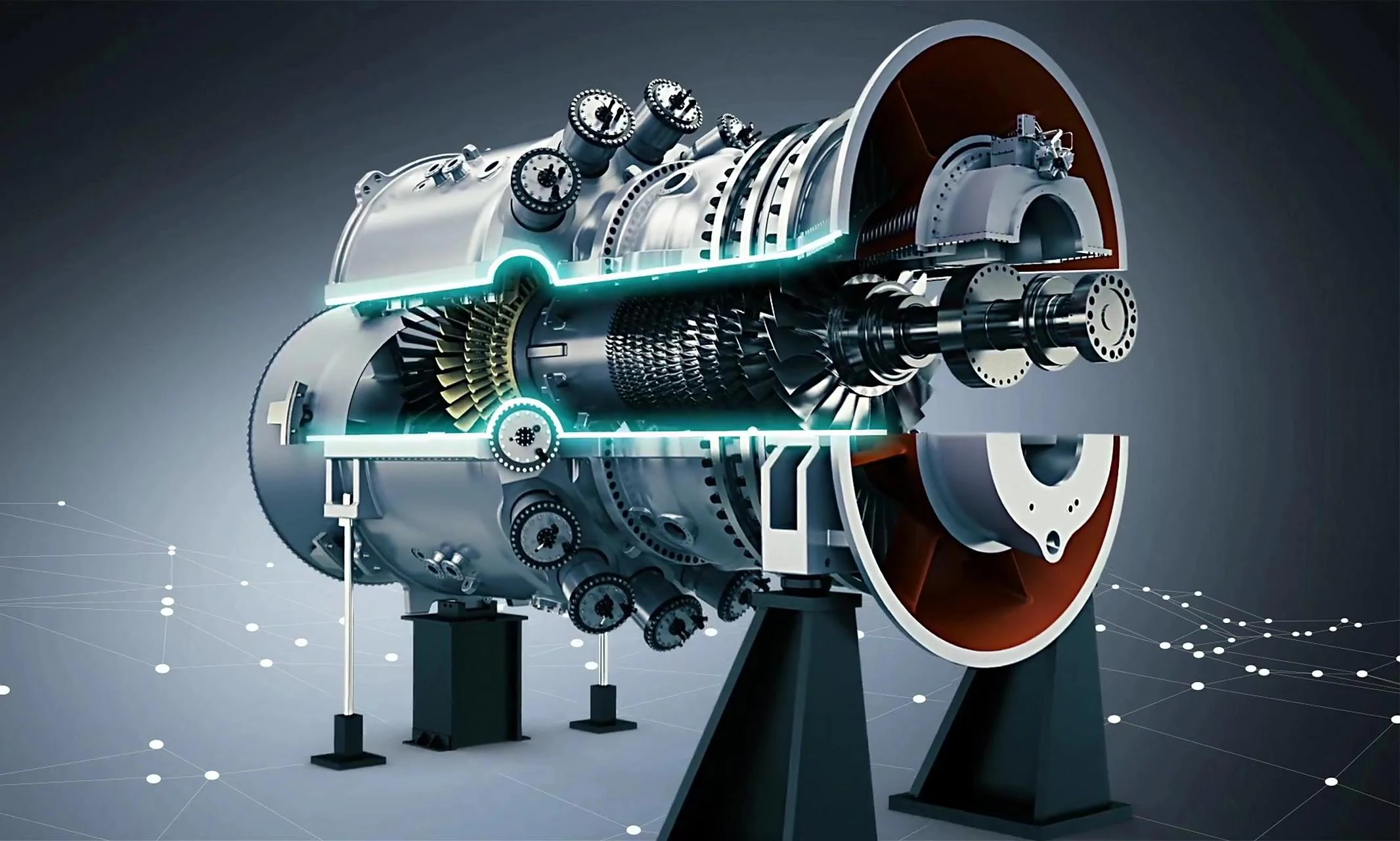
Gas turbines, as a clean energy source, offer advantages such as rapid start-up and shutdown along with high efficiency.
Key components of their stator parts primarily include: compressor bearing housings, compressor stator blade rings, turbine rings, and exhaust diffusers.
As a critical component for mounting stator blades (see Figure 1), compressor rings share similar structures but require diverse machining methods.
During machining, multiple changes in clamping positions are necessary to complete processing.
Due to the lack of systematic and standardized machining approaches for different retaining ring types, operators may employ varying methods and parameters.
Additionally, CNC programming efficiency remains low, with significant repetitive tasks during programming increasing setup time and reducing production efficiency.
This paper aims to systematically summarize and categorize milling machining solutions for gas turbine compressor retaining rings.
It seeks to provide robust technical support for subsequent machining of similar workpieces, enhance CNC programming efficiency, and reduce machining preparation time.

Types of Milling Features for Compressor Retaining Rings
Compressor retaining rings are cast from ZG17Cr1Mo stainless steel, which offers excellent heat resistance, strength, and toughness.
As shown in Figure 2, compressor retaining ring 1 includes a detector mounting slot and a detector mounting hole.
It also has lap joints on both sides of the center parting surface notch.
In addition, it contains top and bottom keyways, inner arc grooves, and belt keyways.
Compressor retaining rings 2 and 3 (see Figure 3) additionally feature circular clamping plate slots on the horizontal center plane.
These features are largely non-coplanar. The clamping methods, machining strategies, and tooling solutions for each feature affect one another during processing.
During machining, the CNC programs for different features interconnect and influence each other


Drafting the Milling Process Plan
Machining Equipment
The team selected a floor-type boring and milling machine (see Figure 4) equipped with a Siemens 840D fully digital control system for compressor ring machining.
This machine features X, Y, Z, W, V, U, and B axes, enabling 7-axis CNC control with any 4-axis simultaneous motion.
The X-axis controls the movement of the column.
The Y-axis controls the movement of the headstock.
The Z-axis controls the movement of the boring spindle.
The W-axis controls the movement of the ram.
The V-axis and B-axis control the linear and rotary movements of the rotary table, respectively.
The U-axis is an additional rotary table mounted parallel to the X-axis, and it controls the movement of the saddle.

Process Plan
Considering the structural characteristics of the compressor ring holder, the milling process must ensure both production quality and production efficiency.
To achieve this, the engineers divide the machining into three setups
Each setup maximizes the number of features machined without requiring a change of tooling heads or re-clamping the workpiece.
First Setup (see Figure 5): With the workpiece in assembled state, position it at the table center with the end face upward.
Orient the upper half toward the +X direction, keeping the center plane parallel to the Z-axis. By rotating the turntable, machine the detector mounting slot and holes.

The second setup (see Figure 6) separates the workpiece into upper and lower sections.
With the end face oriented upward and the center parting surface facing the spindle, the operators use this configuration to machine the center parting surface section.
Simultaneously, the rotary table resolves positioning issues in this state, enabling the single setup to also machine both side shoulders and the keyway on the back.

The third setup (see Figure 7) positions the end face toward the spindle with the center parting surface facing downward.
This configuration is used to machine the internal arc groove and mill the belt notch section.

√ CNC Program
During milling operations, program the CNC according to the following steps:
1) Align the retaining ring concentrically with the rotary table.
Using the table center as the rotation axis, rotate the rotary table to machine the detector mounting slots and holes on the retaining ring’s outer wall.
2) Position the center plane facing the spindle. Machine the center plane notch, center plane clamping plate groove, and screw holes.
3) Rotate the turntable so that both sides of the retaining ring face the spindle, then machine the flange sections on both sides.
4) Rotate the turntable so that the back of the retaining ring faces the spindle, then machine the keyway section on the back.
5) With the center plane facing downward, machine the internal arc groove, mill the belt notch, and drill and tap the internal threaded hole within the notch.
Tooling Solutions
Engineers configured corresponding tooling solutionsfor the milling operations of different gas turbine compressor support rings.
During programming, operators must clearly specify the tools for each machining step. Table 1 lists the existing machining features and their corresponding tooling solutions.

Considerations for tool selection are outlined below.
1)For various types of notched surfaces, the difference between the surface radius (R) and the notch size plays an important role in tool selection.
If this difference is too large, and the operator continues to use tools with a cutting radius less than or equal to the surface radius (R), the operator must perform multiple layered milling operations.
This increases the number of passes and ultimately reduces machining efficiency.
Therefore, the operator performs roughing using a milling cutter with a cutting radius greater than R, and then finishes with the original tool.
2) When machining slots with bottom radii, use a milling cutter with a matching radius.
Alternatively, machine the base and sides first, leaving a bottom radius allowance, then run a separate program to mill the radius.
3) When machining arc slots, carefully calculate the tool holder dimensions and the clearance between the workpiece’s inner circle to prevent interference.
CNC Programming
Zero Point Setting
The zero point setting for compressor retaining rings varies under different clamping conditions, but the selected reference surfaces should be as consistent as possible.
For integral machining (coordinate system shown in Figure 8), the zero points are set as follows: X0 is the horizontal center plane, Y0 is reference surface A, Z0 is the cylinder center.
When the center plane is parallel to the Z-axis, B0 is set.

When machining facing the center axis with the median plane (coordinate system shown in Figure 9), the zero points are set as follows: X0 is the center position of the inner circle, Y0 is the axial reference plane, and Z0 is the horizontal median plane.

When machining with the median plane facing downward (see Figure 10 for coordinate system), the zero points are set as follows: X0 is the center position of the inner circle, Z0 is the axial reference plane, and Y0 is the horizontal median plane.

When machining both sides facing the spindle (coordinate system shown in Figure 11), the zero points are set as follows: Z0 is the center position of the inner circle, Y0 is the axial reference plane, X0 is the horizontal center plane.

Programming
To reduce machining setup time, the machining program is modularized by features.
Based on this, engineers developed a universal subroutine to parameterize critical dimensions.
This allows only the assignment of critical dimensions within the main program, minimizing repetitive programming time.
Additionally, when multiple instances of similar features exist at different locations, programmers utilize the REPEAT block read function.
This consolidates all location data into a single programming location, facilitating program creation and verification while enabling continuous machining execution.
The REPEAT block content is shown below.
.jpg "(1)")
The main features are classified as follows:
1. Rectangular Slots
Including the back keyway (see Figure 12) and the detector mounting slot (see Figure 13).


Taking the detector mounting slot as an example, the program sets the detector’s length, width, depth, tool radius, and cutting depth as parameters.
During rough and finish machining, operators only need to replace the tool and modify the tool radius.
The feed path for the detector mounting slot (see Figure 14) and the corresponding program are as follows, with feed data listed in Table 2.


")
2. Rectangular Opening Grooves (see Figure 15)
Include belt opening grooves (see Figure 16) and center parting surface opening grooves (see Figure 17). The programming for these features is relatively complex.
In addition to setting the length, width, depth, tool radius, and cutting depth of the belt opening groove, engineers also define several other parameters.
These additional parameters include the groove opening direction, the perimeter allowances, and the bottom allowances.
They also include the feed rate along the groove width.
The main program for the belt opening groove is shown below.
")


N5 G90 G17 G54 T1 D1
N10 TRANS Z55
N15 G00 Z100
N20 M03 M42 S1500 F200
N25 RO1=11 R02=100 R03=0 R10=10 R11=150 R12=46 R13=17;R01: Machining Method.
① Standard Slot [11-Roughing, 12-Contour Milling (Z-Layered), 13-Contour Milling (Z-Nonlayered), 14-Bottom Surface Finishing Tool].
② Typical Slot [21-Roughing, 22-Contour Milling (Z-Layered), 23-Contour Milling (Z non-layered), 24-Bottom finishing cut].
R02: Return position.
R03: Stock position, i.e., starting machining depth.
R10: Slot bottom radius, must not be less than tool radius.
R11: Slot length (along opening edge direction).
R12: Slot width (perpendicular to opening edge direction).
R13: Slot depth (Z).
N30 R14=22.5 R16=0 R17=0.5 R22=20 R23=5;
R14: Slot opening direction angle, 0 is positive X-axis direction, 90 is positive Y-axis direction, 180 is negative X-axis direction, 270 is negative Y-axis direction.
R16: Side wall allowance.
R17: Slot bottom allowance.
R22: Feed rate in slot width direction; invalid during bottom surface finishing (calculated directly based on tool diameter).
R23: Z-axis depth feed rate; invalid during contour milling (Z non-layered) and bottom surface finishing (single-pass depth).
")
3. Hole Types
Includes various countersunk holes, deep holes, and boring holes on the center-split clamping plate groove (see Figure 18).
Operators machine hole features directly using modular programs such as CYCLE82, CYCLE83, CYCLE840, and CYCLE86, which perform drilling, countersinking, tapping, and boring.
Before calling these cycles, programmers convert the coordinate axes to the hole center position using the TRANS and ROT functions.
Alternatively, programmers complete positioning using the MCALL module.
The main programs for milling and drilling holes in the center-split clamping plate groove are as follows:
")

Throughout the entire machining process, operators replace programs for different steps with the corresponding statements or fixed cycles based on the actual machining content.
They then adjust the cutting parameters according to the values required for the current tool.
The actual workpiece is shown in Figure 19.

Conclusion
Researchers developed a comprehensive set of manufacturing methods through their study of the milling process for gas turbine compressor ring bearings.
They also identified appropriate tooling solutions.
In addition, they established standardized CNC programming specifications.
In actual production, this approach effectively eliminates repetitive programming tasks.
It significantly enhances machining efficiency for similar workpieces.
It also improves equipment utilization and streamlines process transitions.
Additionally, it helps shorten overall production cycles.
It also contributes to elevating the machining quality and performance of gas turbine compressor support rings, thereby ensuring stable turbine operation.
This achievement represents a dual breakthrough in production.It enhances both production capacity and quality optimization.
It fully validates the practical value of synergistically optimizing the various process elements.

