
With the rapid development of industries such as aerospace, high-end equipment, and electronic devices, precision electromechanical components are evolving toward higher precision, greater complexity, and miniaturization.
This trend places increasingly stringent demands on manufacturing processes.
For instance:
– Aircraft engine turbine blades require profile accuracy controlled within ±0.02 mm and surface roughness Ra not exceeding 0.8 μm;
– Smartphone mid-frames must achieve complex surface precision while enabling efficient mass production.
Traditional machining processes struggle to meet these demands.
High-speed, high-precision CNC machining integrates high-speed cutting, precision control, and intelligent technologies.
This approach overcomes the efficiency and accuracy limitations of conventional methods and has become a key technology for precision electromechanical component manufacturing.
Precision CNC machining processes integrate high-speed cutting, precision control, and intelligent technologies.
They overcome the efficiency and accuracy limitations of conventional methods and have established themselves as key technologies for precision electromechanical component manufacturing.
Based on this, this paper explores the application of high-speed, high-precision CNC machining processes in rough machining, finish machining, and complex shape machining.
The focus is on precision electromechanical components. Optimization strategies are proposed from the perspectives of equipment, cutting tools, parameters, and CNC programming.
Overview of High-Speed, High-Precision CNC Machining Processes
High-speed, high-precision CNC machining processes represent an advanced manufacturing technology.
They achieve high cutting speeds, high feed rates, and high-precision machining on CNC equipment by optimizing machine tool performance, tool paths, and process parameters.
Its core characteristics include high speed (spindle speeds exceeding 10,000 r·min-1, feed rates ranging from 20 to 100 m·min-1), high precision (accuracy controlled within ±5 μm, surface roughness Ra not exceeding 0.8 μm), and digital drive systems.
The technological framework encompasses hardware support, such as high-speed machine tools, super-hard tool materials, and high-precision CNC systems.
It also includes process strategies, such as cutting parameter optimization, smooth tool path planning, and minimal quantity lubrication.
Application of High-Speed, High-Precision CNC Machining Technology
Application in the Rough Machining Stage of Components
The core of rough machining lies in establishing a process balance between “efficient material removal and stable residual allowance.”
Technologically, this involves precisely regulating cutting energy to achieve synergy between material removal efficiency and machining stability.
High-speed, high-precision CNC machining combines high rotational speeds (15,000–30,000 r·min-1) with large feed rates (20–50 m·min-1), enabling cutting line speeds that surpass traditional process limits.
Parameter matching is not a simple combination of rotational speed and feed rate values. Instead, it is a systematic energy dispersion strategy based on material cutting mechanisms.
This strategy distributes cutting energy across more material units per unit time, increasing material removal rates while simultaneously controlling peak cutting forces at lower levels.
This fundamentally reduces the fluctuation in allowances caused by workpiece deformation under stress.
The dynamic response capability of the CNC system is the key enabler for achieving this goal.
The load adaptive mechanism, based on model predictive control algorithms, dynamically corrects feed rates within milliseconds by analyzing cutting force characteristics in real-time through spindle current signals.
Its core logic establishes a mapping relationship between cutting force and material allowance.
Upon detecting sudden changes in allowance or fluctuations in material hardness, it proactively adjusts feed parameters to suppress load fluctuations (amplitude not exceeding 5 μm).
This approach prevents abnormal tool wear caused by overload while ensuring uniformity in blank allowance.
For thermal error control, the dual-closed-loop cooling system employs internally cooled tools to directly extract cutting heat from the cutting zone.
Combined with real-time coupled regulation of flow rate and temperature, it maintains workpiece temperature rise within ±2°C, preserving stable dimensional references for subsequent finishing operations.
Its technical value lies not only in minimizing thermal deformation but also in establishing a repeatable machining environment.
Application in the Precision Machining Stage of Components
Precision control in finishing operations involves error tracing and compensation under multi-physics interference, with the key lying in quantifying error sources and implementing targeted corrections.
High-speed, high-precision CNC machining achieves stable dimensional accuracy within ±5 μm by establishing a closed-loop system of “measurement-modeling-compensation.”
From a kinematic perspective, positioning errors in machine tool feed systems result not from a single factor but from the coupling of initial positioning errors, thermal errors, and load errors.
» Thermal Error Compensation and Dynamic Adaptation
Compensating for thermal errors requires moving beyond simple linear temperature-deformation relationships.
This is achieved by constructing three-dimensional temperature field models for spindles and guideways through multi-point temperature acquisition, combined with dynamic correction using thermal deformation coefficients under varying operating conditions.
This correction is not a static parameter substitution but a dynamic adaptation based on real-time temperature gradients.
The core challenge is to capture the nonlinear mapping relationship between the temperature field and the deformation field.
» Surface Quality Control and Tool-Lubrication Strategies
Controlling machined surface quality by addressing the tribological mechanisms at the tool-workpiece interface.
Combining super-hard tools (hardness 3,500–4,500 HV) with micro-lubrication technology, tool edge parameters like radius and rake angle are matched to workpiece material hardness.
Precise lubricant delivery—guided by material friction characteristics and cutting temperature requirements—establishes microenvironmental equilibrium in the cutting zone.
The selection of super-hard tools addresses tool wear resistance during high-speed cutting.
Micro-lubrication technology, on the other hand, forms a continuous lubrication barrier in the cutting zone through the atomization properties of oil mist particles.
This barrier alters the friction coefficient between the tool and chips, suppressing the synergistic effects of adhesive wear and diffusion wear, thereby stabilizing surface roughness Ra below 0.4 μm.
For face machining, a constant linear speed control strategy ensures the dynamic accuracy of CNC machine tools.
This strategy dynamically adjusts spindle speed based on cutting diameter to maintain constant linear cutting edge speed.
This counteracts cutting force fluctuations caused by diameter variations.
It fundamentally prevents surface chatter and provides micro-topography assurance for the functional realization of precision-fit components.
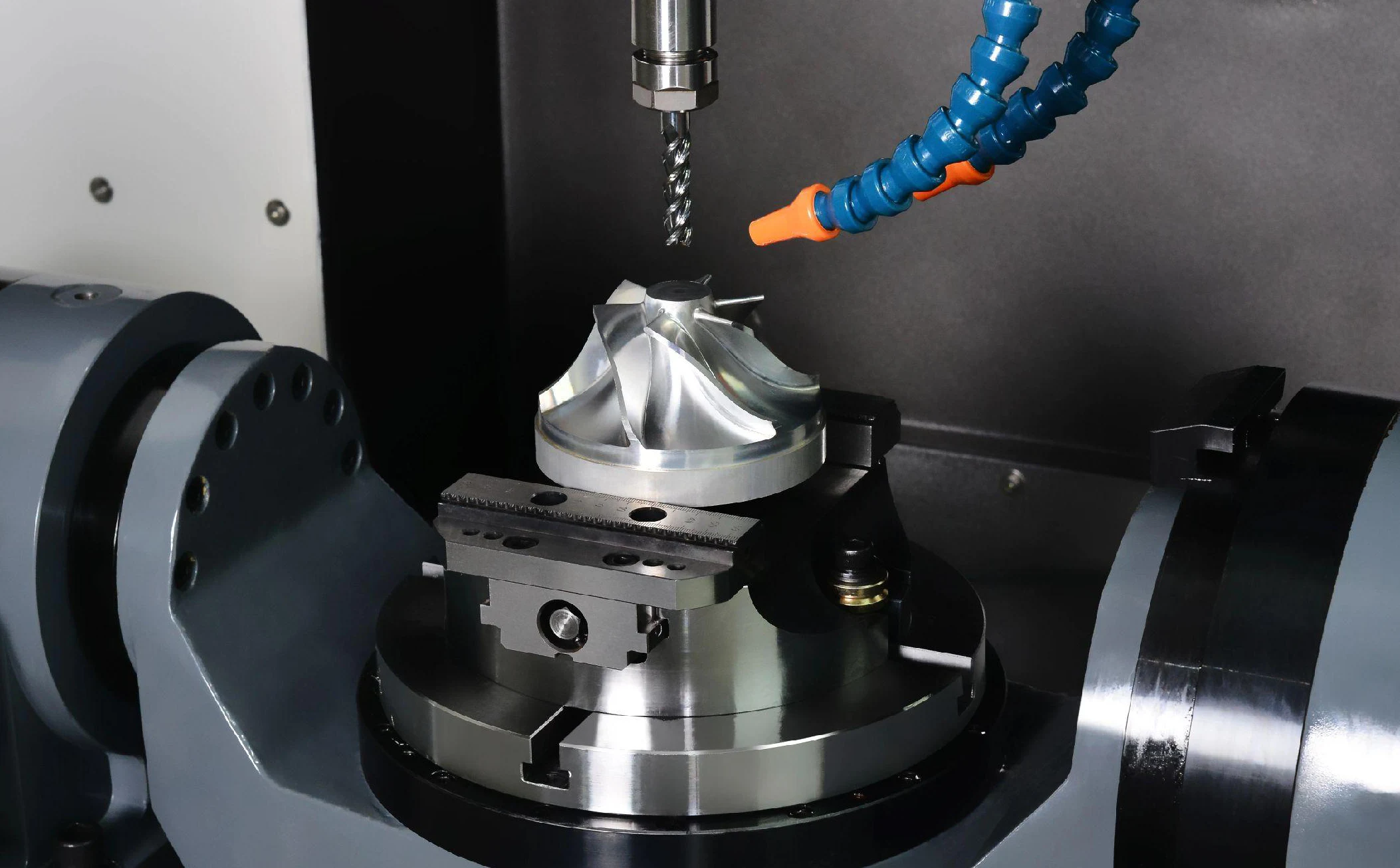
Application in Machining Complex-Shaped Components
In machining complex-shaped components, five-axis simultaneous technology overcomes spatial constraints by establishing precise mapping between multi-degree-of-freedom motion and intricate geometric features.
Five-axis machines dynamically adjust tool orientation through combined rotational and linear axis movements, ensuring cutting forces consistently align with the workpiece’s principal stiffness axis.
This fundamentally eliminates interference issues inherent in three-axis machining, controlling distortion errors on curved surfaces to ±0.02 mm.
Toolpath planning must align with the machine’s dynamic characteristics.
The continuous interpolation strategy based on B-spline curves reduces vibration caused by motion impacts by controlling the rate of curvature change.
Intelligent parameter adjustment, relying on feature recognition and material mechanics analysis, dynamically adjusts the tool axis vector and feed rate for weak-rigidity areas such as thin walls and sharp corners.
This directs cutting forces to the most rigid regions, achieving stable control of geometric tolerances for complex-shaped parts and fundamentally overcoming the technical bottlenecks of traditional machining.
Optimizing High-Precision CNC Machining
Although high-speed, high-precision CNC machining serves as a core technology for precision electromechanical component manufacturing, bottlenecks persist in practical applications.
Spindle vibration, guideway clearance, and multi-source error coupling compromise dimensional stability;
Inadequate tool adaptation and life management struggle to meet diverse material machining demands, and wear frequently leads to quality issues.
Fixed cutting parameters fail to adapt to fluctuations in blank allowances and material hardness.
Programming relies heavily on experience and lacks sufficient closed-loop verification, resulting in low efficiency and high risks.
Additionally, fragmented process data hinders precise optimization.
Therefore, multidimensional optimization is essential to unlock the full potential of this technology.
Optimized Machining Equipment
Enhanced the dynamic performance of the machine tool motion system by replacing conventional mechanical spindles with magnetic levitation spindles.
Electromagnetic force enables non-contact support, eliminating vibration interference and controlling radial runout within 2 μm.
This optimization is particularly suitable for machining components requiring high stability, such as precision gears.
High-Precision Scraping Feed System The guideways, paired with a preload adaptive adjustment mechanism, control the clearance between guideways and slides or related moving components to below 1 μm.
This reduces backlash error and enhances precision for complex contour trajectories.
For error compensation, a laser interferometer captures positioning errors at a 10 kHz sampling rate.
It establishes a nonlinear compensation model incorporating operational duration and load variations, controlling long-term cumulative errors within 3 μm.
A multi-sensor fusion monitoring system integrates data from acoustic emission sensors, infrared temperature sensors, and accelerometers.
Combined with deep learning algorithms, it issues early warnings 5 to 10 minutes in advance to prevent precision degradation.
For environmental regulation, an air-static pressure isolation platform is added to the constant temperature and humidity environment, filtering external vibration frequencies between 1 and 100 Hz.
A zoned air conditioning control strategy maintains a temperature difference of less than 0.5°C between processing and non-processing areas.
A micro-air pressure balancing system controls pressure fluctuations within ±5 Pa, preventing airflow interference during high-precision machining.
Optimizing Tool Design and Management
Precisely match tool materials to the characteristics of the workpiece material.
When machining aluminum alloys, polycrystalline diamond tools are recommended due to their high hardness and low friction coefficient, which significantly reduce cutting forces and surface roughness.
For instance, in machining aluminum alloy smartphone frames, polycrystalline diamond milling cutters can control surface roughness Ra below 0.4 μm.
For difficult-to-machine materials like titanium alloys, cubic boron nitride (CBN) tools are an excellent choice.
These tools deliver outstanding high-temperature wear resistance, enabling stable operation at cutting temperatures exceeding 600°C.
In aerospace engine blade machining, CBN tools achieve over five times the tool life compared to carbide tools.
Optimizing tool geometry—such as increasing the helix angle of end mills from 30° to 45°—effectively enhances chip evacuation and cutting stability.
Applying TiAlN coating technology reduces the risk of tool-workpiece adhesion and minimizes cutting heat. Implementing a tool life management system records cutting time, length, and other data via sensors.
Combined with wear models, it predicts remaining tool life.
When remaining life reaches a preset threshold, the system automatically alerts operators to replace tools, preventing dimensional deviations and surface quality degradation caused by excessive wear.
Dynamic Adjustment of Cutting Parameters
Based on actual conditions, dynamically adjust parameters through cutting simulation and real-time monitoring.
Utilize simulation software such as AdvantEdge and Deform to simulate the effects of different cutting parameters (cutting speed, feed rate, depth of cut, etc.) on cutting force, temperature, and tool wear, thereby establishing a process parameter database.
During actual machining, strain gauge cutting force sensors are mounted on tool holders to collect real-time cutting force data.
When the cutting force exceeds a set threshold—such as 120% of the average cutting force—the CNC system automatically reduces the feed rate by 10% to 20% to prevent tool breakage.
Optimized Programming and Process Planning Methods
Employ advanced computer-aided manufacturing (CAM) software to achieve efficient programming.
For instance, HyperMill software’s adaptive milling function automatically generates optimized toolpaths based on part geometry.
When machining complex mold cavities, strategies like helical entry and cycloidal milling minimize abrupt toolpath changes, reduce machine feed rate fluctuations, and enhance processing efficiency.
Parametric programming technology enables rapid generation of new machining programs by modifying key parameters, making it particularly suitable for series production.
Introducing Artificial Intelligence (AI) algorithms to analyze part features enables automatic recommendations for tool types, cutting parameters, and machining sequences.
For precision gear machining, AI algorithms can automatically select suitable hobs based on parameters like gear module, tooth count, and material, while planning toolpaths for roughing, semi-finishing, and finishing operations to avoid collision risks.
Before machining, virtual verification is conducted using simulation software like Vericut.
This software simulates machine tool movements, tool trajectories, and cutting processes to proactively identify issues such as collisions, interference, overcutting, or undercutting.
Concurrently, a process optimization feedback mechanism is established.
It compares actual machining data—including dimensional errors and surface roughness—with simulation results, enabling programming parameter optimization.
This creates a closed-loop process optimization cycle: “Simulation → Machining → Optimization.”
Establishing a Closed-Loop Process Data Optimization System
In-depth mining and application of process data form the core foundation for the continuous optimization of high-speed, high-precision CNC machining processes.
An industrial data acquisition system covering the entire machining workflow has been established.
It captures real-time machine tool operating parameters (spindle speed, feed rate, cutting current, etc.), environmental parameters (temperature, humidity, vibration, etc.), and quality inspection data (dimensional errors, surface roughness, etc.).
This process constructs a comprehensive process sample database.
Simultaneously, apply clustering algorithms for hierarchical data analysis to identify critical parameter thresholds affecting machining accuracy.
For instance, when spindle vibration amplitude exceeds 3 μm, dimensional error fluctuations increase by 20%, providing data-driven support for process parameter optimization.
A mapping model linking “processing parameters—process data—quality outcomes” is established.
Combined with partial least squares regression analysis, this model deciphers the nonlinear relationship between cutting speed, feed rate, and surface roughness.
During machining, this model enables the retroactive determination of optimal parameter combinations, enhancing surface quality stability.
Additionally, a self-iterating process parameter module was developed.
It automatically feeds quality deviation data from each batch back into the parameter library.
Using genetic algorithms, it iteratively updates recommended parameters, forming a closed-loop mechanism of “data collection—analysis—optimization—application.”
This enables dynamic evolution of process parameters, continuously improving the pass rate for machining complex parts.
Conclusion
High-speed, high-precision CNC machining processes demonstrate significant technological advantages in the manufacturing of precision electromechanical components.
They effectively enhance both production efficiency and product quality.
Comprehensive optimization strategies—ranging from equipment hardware upgrades and intelligent programming to closed-loop optimization of process data—provide viable solutions for addressing critical challenges in process application.
FAQ
What is high-speed, high-precision CNC machining, and why is it important?
High-speed, high-precision CNC machining is an advanced manufacturing technology that combines high spindle speeds, high feed rates, and micron-level accuracy. It is essential for producing precision electromechanical components with complex geometries and tight tolerances, especially in industries such as aerospace, electronics, and high-end equipment manufacturing.
How does high-speed CNC machining improve rough machining efficiency and stability?
In rough machining, high-speed CNC processes distribute cutting energy more evenly through high rotational speeds and feed rates. This approach increases material removal rates while reducing peak cutting forces, minimizing workpiece deformation and ensuring uniform residual allowance. Adaptive load control further stabilizes the process by dynamically adjusting feed rates in real time.
How is dimensional accuracy ensured during high-precision CNC finishing operations?
Dimensional accuracy is achieved through a closed-loop system that integrates real-time measurement, thermal modeling, and error compensation. By dynamically correcting thermal deformation, positioning errors, and load-induced deviations, high-precision CNC machining maintains dimensional tolerances within ±5 μm and consistently achieves superior surface quality.
Why are five-axis CNC machines critical for machining complex-shaped components?
Five-axis CNC machining enables simultaneous multi-directional tool movement, allowing precise control of tool orientation and cutting forces. This capability eliminates interference, reduces distortion on curved surfaces, and ensures geometric accuracy for complex components, making it indispensable for molds, turbine blades, and intricate electromechanical parts.
How do tool selection and cutting parameter optimization affect machining quality?
Selecting appropriate tool materials—such as polycrystalline diamond for aluminum alloys or CBN for titanium alloys—significantly enhances wear resistance and surface finish. Dynamic optimization of cutting parameters, supported by real-time monitoring and simulation, prevents tool overload, reduces thermal effects, and ensures consistent machining quality.
What role does closed-loop data optimization play in high-precision CNC machining?
Closed-loop data optimization integrates real-time process data, quality inspection results, and intelligent algorithms to continuously refine machining parameters. By establishing a feedback mechanism between machining outcomes and process settings, manufacturers can achieve adaptive optimization, improved consistency, and higher pass rates for precision electromechanical components.

