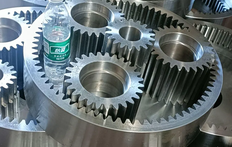
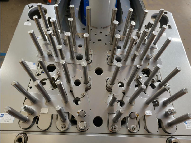
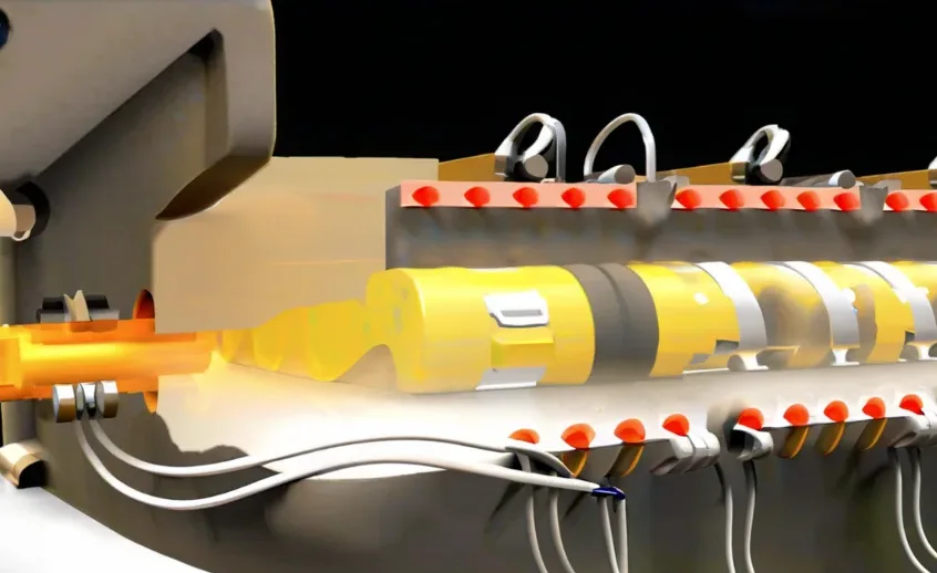
Five-axis CNC machining centers were not initially popular for processing straight and helical cylindrical gears.
These gears were generally processed using hobbing, gear insertion, and grinding methods.
The use of traditional processing methods for large modulus gear processing, especially for helical gears, herringbone gears, and curved gears, has several drawbacks.
Not only is the processing speed slow, but the processing quality is also not high.
Additionally, the processing cost is expensive, and the processing process is not well-matched.
In the processing of small module gears with not many teeth, the use of a small hobbing machine often lacks sufficient processing performance.
The use of a large hobbing machine, on the other hand, is not suitable due to the small size of the gear.
As a result, there is a lack of practical and efficient processing methods for these types of gears.
With the continuous enrichment and improvement of multi-axis machining centers, many of the above problems can be effectively solved.
The processing speed is more than twice that of traditional processing methods. The processing accuracy can reach at least 5 levels.
This ensures that the different specifications of each gear processing step are met.
To this end, the article focuses on exploring the five-axis CNC machining center helical gear processing technology.
Helical gear tooth formation and processing technology
Helical gear tooth formation
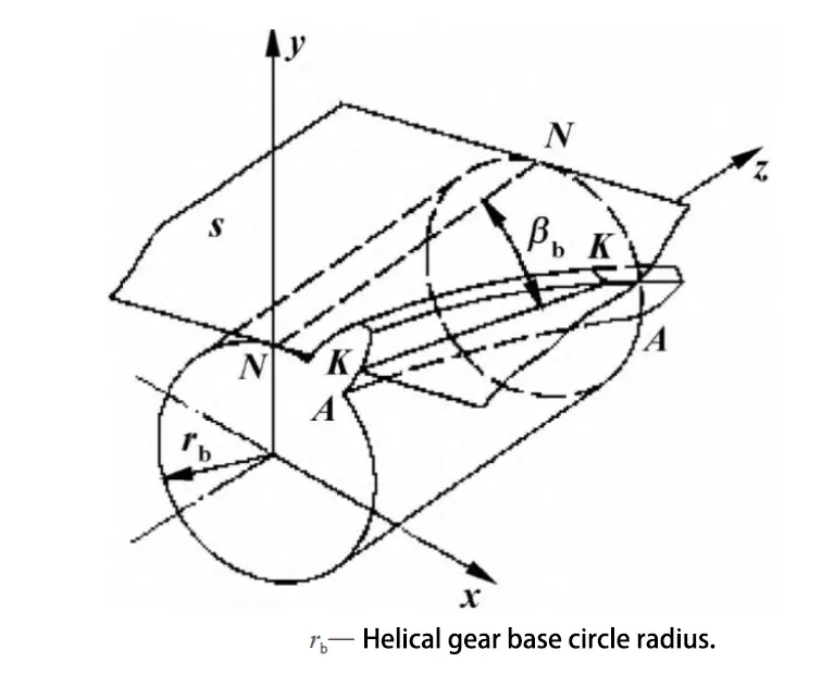
Helical gear refers to the tooth shape and gear axis between the corresponding angle of the gear, the gear tooth formation principle shown in Figure 1.
The generating surface S is always rolling tangentially to the outer surface of the base cylindrical surface. The angle between the tangent line of the two and the base cylindrical base line NN is βb.
The helical line KK constitutes the tooth surface of the helical gear. This helical line is known as the involute helical surface.
The intersection line between the helical surface and the gear end is an involute.
However, the intersection lines generated by the involute helical surface and the outer surface of the cylindrical surface are all helical lines.
The acute angle βb formed by the tangent of helix AA and the gear axis is the base circle helix angle.
The larger the value of βb, the higher the helical inclination of the helical gear; when the value of βb is zero, the gear becomes a spur gear.
Helical Gear Machining Process
In the processing of helical gears, a series of processing technologies must be adopted. As shown in Figure 2, these technologies are part of the overall process.
In this process, the milling (rough and finish milling tooth shape) processing step can use the following three main processing methods:
First, the use of traditional spiral milling machine for helical gear tooth milling;
Second, processing with the help of EDM wire cutting equipment, but the processing speed is very slow;
Third, the use of five-axis CNC machining centers for processing is implemented. A good processing program is set up.
This allows the machining process to be carried out independently, with a fast processing speed. It also meets the requirements for helical gear processing.
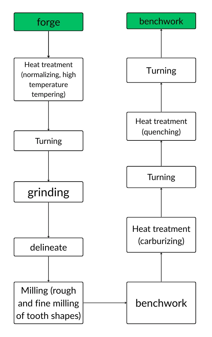
Helical gear five-axis machining process
After an in-depth analysis of the appearance characteristics of helical gears and application requirements, the processing steps are determined.
These steps for the helical gear CNC machining center are as follows:
First, use three-axis / five-axis CNC machining centers to complete the rough machining of tooth shape;
Secondly, semi-finish machining with 5-axis CNC machining center;
Again, using five-axis CNC machining centers for finishing; finally, remove the helical gear tooth root.
In the process of helical gear processing, you need to combine the helical gear drawings and requirements to determine the appropriate processing machine.
In addition, the accuracy of helical gear machining and processing speed are affected by several factors.
These factors include tool specifications, tooth parameters, precision requirements, and gear rigidity.
Determine the processing equipment
In helical gear processing, it must have a rotary function, so in order to realize the processing of helical gears, select the four-axis machining center.
In the machining process, the helical gear blank is fixed on the equipment turntable. One axis carries out the rotary movement.
The remaining axes are responsible for controlling the tool to complete the tooth milling.
Based on this, the selection of five-axis CNC machining centers for helical gear machining can meet the necessary conditions for helical gear machining.
Determine the machining tool
In the use of five-axis CNC machining centers for helical gear processing, you can choose cylindrical milling cutter or finger milling cutter processing.
First of all, in the selection of a cylindrical milling cutter for helical gear tooth shape processing, the limitation of the helical gear tooth pitch must be considered.
Due to this limitation, the cylindrical milling cutter specification that can be chosen is small, and the tool strength is low.
As a result, only a small cutting feed can be used, leading to slow processing speeds. Therefore, it is recommended to prioritize using the appropriate finger milling cutter.
Finger Milling Cutter: Benefits and Limitations
However, in the actual use of a finger milling cutter for the tooth milling process, the tool size is often small relative to the gear tooth specifications.
As a result, during processing, tool breakage is more likely to occur. This issue is not conducive to improving the speed of helical gear tooth processing.
Therefore, under the premise of conditions allow, to use a larger diameter disk milling cutter as far as possible.
Disk Milling Cutter: Enhancing Machining Speed and Overcoming Challenges
Compared with finger milling cutters, disk milling cutters have excellent strength properties, which can effectively improve the machining speed of helical gear teeth.
However, there are some shortcomings in the use of disk milling cutters for milling, highlighted by the difficulty in determining the diameter of the disk milling cutter.
When the diameter of the selected disk milling cutter is large, the machining process is very easy to lead to the processing of the tooth shape is not complete;
When the diameter of the selected disk milling cutter is small, the clearance between the shank and the gear teeth is very small, which is easy to produce interference.
Interference may occur between the shank and the top of the tooth during tool cutting.
Therefore, when the machined helical gear module and tooth number are small, the finger milling cutter is preferred for tooth machining;
On the contrary, when the machining of the helical gear module and the number of teeth is large, priority is given to the use of disk milling cutter for tooth shape processing.
Selection of suitable fixtures
In the choice of five-axis machining center for helical gear tooth shape processing, to choose a special fixture.
In the clamping process, first of all, the special fixture should be installed on the five-axis CNC machining center work platform, and then the helical gear blank is fixed to the special fixture.
In the process of helical gear tooth shape processing, after completing the processing of one tooth shape, the five-axis machining center will control the special fixture to rotate to the corresponding angle.
Then, the machining center will continue to process the next tooth shape. This cycle repeats until all tooth shapes are processed.
Determine the tool processing trajectory
In the use of five-axis CNC machining centers for helical gear tooth shape processing, determining the tool machining trajectory is very important.
The trajectory is then divided into a number of points. Through the corresponding post-processing, the five-axis CNC machining program is obtained.
In the helical gear machining process, roughing and finishing need to be independent.
In fact, the two machining processes are similar in their processing method. However, there is a big difference in the selection of processing tools.
Generally speaking, the tool trajectory includes two parts, respectively, tooth roughing trajectory and tooth finishing trajectory.
CNC machining center machining helical gear tooth shape tool trajectory
First, the rough machining of the gear blank.
The selected CNC machining center is used for contour milling and rough machining of gear blanks. In this machining segment, a higher strength, larger diameter disk or finger milling cutter is used.
The depth of feed is increased to remove excess material from the blanks in the shortest possible time. This prepares the blanks for the next step of semi-finishing machining.
During the machining of helical gears, only one machining program needs to be generated, as each tooth profile is the same.
In general, the process of toolpath formation is:
The “machining – roughing – contour roughing” machining process is used. The machining target is determined based on the actual situation.
Then, the feed point, machining side, and tool movement direction are determined in sequence.
In the surface machining of helical gears, the milling direction is aligned with the direction of the tooth groove.
If the direction is not reasonable, you can click on the arrow of the starting direction to adjust the milling direction.
After clarifying the milling direction, reasonable milling parameters should be set.
In the planning of roughing tool parameters, milling is carried out in layers. The machining depth is set to be about 4 mm each time.
After completing this process, the roughing tool path for a single tooth groove of the helical gear is obtained.
Second, gear profile finishing.
After completing the rough machining of the gear blank, it is necessary to carry out the finishing of the gear profile. This is generally done using a finger or disk milling cutter with good strength and a small diameter.
The gear tooth shape is then machined to match the required dimensions specified in the drawings. Additionally, the tool compensation method is set to use left compensation.
When performing gear profile finishing, the trajectory construction process is:
The “machining – finishing – contour finishing” process is used as the machining strategy. The machining target is determined based on the actual situation.
Then, in sequence, the feed point, machining side, and direction of tool movement are specified. This completes the setup of the processing parameters.
In the finishing process, the tool path planning does not require the use of layered milling.
This helps ensure that the completed tooth profile has good surface roughness. After that, a single groove finishing tool path for the helical gear can be obtained.
Third, clear root machining.
After the completion of the helical gear profile finishing, it is common for some areas to show incomplete cutting.
To ensure the machining accuracy of the gear grooves, root processing must also be performed during the finishing stage.
This additional step helps to further improve both the gear processing accuracy and the surface roughness.
Cutting trajectory simulation and export code
After setting the cutting trajectory of the tool, the cutting trajectory simulation should be carried out to see whether there is any unreasonable phenomenon in the tool movement.
In the actual verification work, it is necessary to plan the blank to be machined. This allows observation of the specific cutting situation of the tool.
The goal is to ensure that there is no overcutting, collision, or other undesirable phenomena during the cutting process.
In order to effectively improve the speed of helical gear cutting and processing, and to reduce processing costs, certain conditions must be met.
One of these conditions is conducting a tool collision and interference check in advance. This ensures safe and efficient machining without compromising the quality or safety of the process.
After confirming that there are no issues in the tool cutting and processing path simulation, the processing code needs to be exported.
At the same time, the obtained program code must undergo post-processing. This ensures that it can be adapted to the code recognition standards of different CNC machining centers.
Helical gear processing
Helical gear blank processing
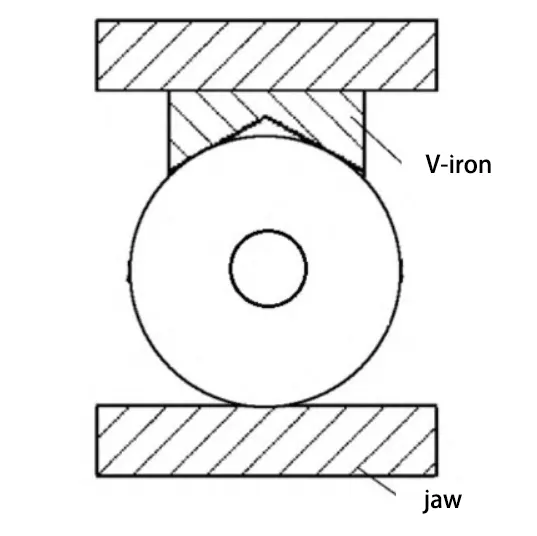
In the helical gear blank processing, the first need to be fixed to the CNC machining table, the actual clamping method shown in Figure 3, the cylinder is the helical gear blank material.
In the gear blank clamping process, in order to prevent damage to the table, you can design a special protection plate under the blank.
In the helical gear blank machining, mainly for the blank of the upper end face, lower end face and the center hole processing.
Tooth shape machining
When machining the teeth of helical gear, first fix the helical gear to the indexing fixture, and determine the tool setting point as the highest point of the outside of the tooth apex circle.
After completing the tool setting process, the 5-axis CNC machining center is turned on to process the first helical tooth profile.
Each time a helical tooth is processed, the indexing fixture automatically rotates to the corresponding angle. Then, the next helical tooth is processed. This cycle continues until all the helical teeth are machined in turn.
Conclusion
At this stage, the use of general machine tools with involute tooth shape of the “modulus milling cutter” for gear processing, but the processing method is limited by the separation of teeth;
In CNC machining, cylindrical and disk milling cutters are used to process gears through the spreading method. However, this processing method often results in radial and axial runout of the tool.
As a result, it is difficult to ensure the machining accuracy of the gear tooth shape.
The article proposes the use of five-axis CNC machining centers for helical gear processing.
This includes the selection of processing equipment, machining tools, suitable fixtures, and the determination of the tool machining trajectory.
During the completion of one tooth shape, the machine tool is able to automatically rotate to the corresponding angle. It then continues to process the next tooth shape.
This method effectively improves the flexibility of tooth shape processing. It also enhances the accuracy and speed of tooth profile machining.
Overall, the approach demonstrates a high value of popularization.
FAQ:
Five-axis CNC machining for helical gears refers to using advanced multi-axis machining centers to cut and form gear teeth with high precision. Unlike traditional hobbing or grinding, five-axis machining allows for faster speeds, better accuracy, and the flexibility to process gears with complex geometries such as helical, herringbone, and curved gears.
Traditional gear processing methods such as hobbing and grinding are slow, costly, and often lack precision for large-modulus or complex gears. They also struggle with small-module gears, where machine size and rigidity become limiting factors. Five-axis CNC machining overcomes these inefficiencies with higher processing speed and tighter tolerances.
Five-axis CNC machining centers can achieve accuracy levels of grade 5 or better, thanks to their ability to precisely control tool movement along multiple axes. This reduces radial and axial runout, ensuring gear teeth are machined with consistent profiles and surface roughness that meet strict industry requirements.
Helical gears, herringbone gears, curved gears, and small-module gears benefit greatly from five-axis CNC machining. These gear types often require complex tooth shapes and high precision that are difficult to achieve with conventional gear processing machines.
Cylindrical milling cutters, finger milling cutters, and disk milling cutters are commonly used. Finger cutters are suitable for smaller gears with fine teeth, while disk milling cutters provide higher strength and machining efficiency for larger gears. The choice depends on gear size, tooth module, and precision requirements.
Tool trajectory planning ensures that roughing, semi-finishing, and finishing steps are executed efficiently without tool interference or overcutting. Proper trajectory planning improves processing speed, enhances surface quality, and minimizes the risk of tool collisions during machining.
Special fixtures are essential to securely hold gear blanks during five-axis machining. The fixture rotates the gear blank automatically after each tooth profile is completed, ensuring precise indexing for subsequent teeth and maintaining overall gear accuracy throughout the process.
Cutting trajectory simulation is crucial for detecting tool collisions, overcuts, and interference issues before actual machining. This reduces processing risks, improves machining efficiency, and ensures the exported CNC code is optimized for safe and accurate gear production.
By combining roughing, finishing, and tooth root machining in one setup, five-axis CNC machining shortens cycle times and reduces the need for multiple machines or processes. This increases efficiency, lowers labor costs, and minimizes material waste, making it a cost-effective gear manufacturing solution.
The key advantages include:
Twice the processing speed compared to traditional methods
High accuracy (grade 5 or better)
Flexibility to machine various gear types and sizes
Reduced costs due to fewer setups and faster cycles
Better surface finish and consistent tooth profiles

