
A CNC gantry milling machine is primarily used for machining large, heavy, and complex parts. These machines are ideal for producing components that require high precision and are typically used in industries like aerospace, automotive, energy, and heavy machinery.
What is CNC gantry milling machine?
A CNC gantry milling machine is a type of computer numerical control (CNC) machine tool designed for precision milling, which involves removing material from a workpiece using rotating cutting tools.
The gantry design refers to a machine structure where the milling head or tool moves along multiple axes, supported by a frame (the gantry) that spans over the workpiece.
Here are key features:
Gantry Structure: The machine features a gantry-type frame where the milling head (spindle) is suspended above the workpiece.
This provides stability and allows for larger workpieces to be machined with high precision.
Multi-Axis Movement: A CNC gantry milling machine typically operates on multiple axes (usually X, Y, Z, and sometimes additional axes like W).
These axes control the movement of the milling head and the workpiece, allowing for precise and complex machining operations.
Heavy Duty: These machines are designed to handle large and heavy workpieces, making them suitable for industries such as aerospace, automotive, and large-scale manufacturing.
High Precision: CNC gantry milling machines offer high precision and repeatability, which are critical for producing parts with tight tolerances and complex geometries.
Versatility: These machines can be equipped with various milling heads and accessories, such as right-angle heads or boring heads, to perform different types of milling operations (e.g., face milling, drilling, boring, and contouring).
Practical examples of processing
Turbocompressor is a large-scale unit combined with many equipments, and the case is one of its core components.
The large gear case has a large volume and heavy mass, making it prone to deformation during the machining process.
Due to processing factors such as machine tool accuracy, cutting tool performance, and measurement errors, it is difficult to meet the design requirements for the bearing hole size and geometric tolerances.
This directly affects the transmission accuracy and service life of the gear.
In order to efficiently process high-quality parts, the tool should ideally complete all the processing in a single clamping.
This approach ensures that the positional accuracy of each surface of the parts relative to each other reaches the highest possible level.
With the development of intelligent manufacturing technology, CNC machine tools are gradually replacing traditional machining equipment.
This is due to their performance advantages, such as high efficiency and high precision.
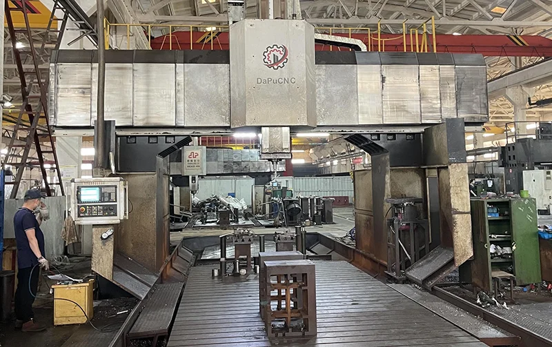
The box has a huge volume, heavy weight, and complex modeling. The design accuracy requirements are also high. Therefore, the CNC gantry milling machine is preferred for processing the box (see Figure 1).

The CNC gantry milling machine is typically equipped with a ram-type boring and milling head mounted on the crossbeam.
This system has three feed axes: table (X-axis), boring and milling head (Y-axis), and ram (Z-axis).
Additionally, a W-axis parallel to the Z-axis is added to the ram on the movable beam.
The ram of the movable beam is equipped with a ram-type boring milling head that has three feed axes: table (X-axis), Y-axis, and ram (Z-axis). Additionally, the ram is equipped with a W-axis parallel to the Z-axis.
This setup is generally paired with a variety of accessory heads, including a right-angle milling head, universal angular head, extension head, and countersinking milling head.
This eliminates the need for repeated clamping, improves work efficiency and reduces work intensity.
Difficulties in the processing of the box
Box is a typical mechanical component, as an important basic framework of the transmission machinery, has a high processing accuracy requirements.
As shown in Figure 2, the parallelism of the high-speed axis and low-speed axis centerline is required to be φ0.5mm. The bearing gearing must also meet the φ0.5mm requirement.
The parallelism of the centerline of the high-speed shaft and the low-speed shaft is required to be φ0.5mm.
The verticality between the bearing stop line and the end face is required to be 0.05mm.
The bearing retainer is symmetrical between the upper and lower sides.
The radial dimensions are φ180 (+0.03/+0) mm and φ160 (+0.03/+0) mm. The axial dimensions are 60 (+0.03/+0) mm and 30 (+0.03/+0) mm.
The sealing stopper has the following radial dimensions: φ 216 (+0.03/+0) mm and φ 160 (+0.03/+0) mm. The axial dimensions are 21 (+0.03/+0) mm and 10 (+0.03/+0) mm.
The concentricity between the sealing hole and bearing hole is required to be φ 0.05mm. Additionally, the surface roughness value of both the bearing hole and sealing hole must be Ra = 3.2μm.
The workpiece belongs to the complex box parts with high requirements of dimensional accuracy, geometric accuracy and surface roughness.

Factors affecting the machining accuracy of the box
(1) Rigidity of the case
The large gear box generally has a length of 2 to 3 meters, with a large volume and heavy weight.
When the workpiece is placed on the machine table, its self-weight can cause distortion and deformation. Additionally, the clamping of the box also affects machining accuracy.
(2) Machine accuracy
In the process of installation and long-term use of machine tools, the precision of the guideway, ram and table will have different degrees of decline.
The company’s CNC gantry milling machine is equipped with seven different milling heads.
During the process of replacing the milling head and steering the milling head, errors may occur.
(3) cutting stress
The large gear box body is generally cast. During the machining process, cutting stress is generated.
As the workpiece undergoes stress release, deformation occurs, which affects the machining accuracy.
In addition, the selection of tools, cutting parameters and positioning and clamping factors can affect the machining accuracy of large gear box.
Solutions
(1) Develop a reasonable technology program
Different process solutions achieve different benefits and consume different labor. After many tests and summarization, the more mature processing route is:
① Rough machining is used to remove large allowances. During rough milling of the large gear bearings and grooves, a 2mm radial unilateral and axial allowance is left on each.
Similarly, when rough milling the pinion wheel bearing block and sealing block, a 2mm radial unilateral and axial allowance is left on each.
②Heat treatment and tempering to eliminate stress.
③Bearing stop bearing gland and box seat with a pin hole, fasten the pin and bolt fastening.
④ As shown in Figure 3, the body box consists of the upper and lower boxes, or the upper, middle, and lower boxes.
These must be bolted together as a whole and include pin holes and fastening pins.
During semi-finishing, each bearing block and sealing block leaves a 0.5mm radial unilateral and axial allowance.
Additionally, aging treatment is applied to eliminate stress.
⑤ Box box finishing.

(2) Ensure the precision of machine tools
In recent years, the company has introduced four sets of CNC gantry milling machines.
Since the roughing and semi-finishing machining processes involve larger cutting volumes, they have a significant impact on the accuracy of the machine.
To address this, the machine tools are organized for division of labor and cooperation.
Two of the machines are dedicated to roughing and semi-finishing machining, while the other two are dedicated to finishing.
In addition, regular inspection and maintenance of each machine tool to ensure the accuracy of spindle rotation, guideway movement and size control.
(3) Gradual elimination of machining stress
Due to the large size of the box, the machining allowance is also significant.
Therefore, multi-step roughing, semi-finishing, and finishing processes are used to gradually remove the machining allowance and effectively eliminate machining stress.
After rough machining, heat treatment and tempering are used to remove stress. Between semi-finishing and finishing, natural aging is applied to further eliminate stress.
This process maximizes the removal of machining stress at each stage, ensuring that all stress is completely released before finishing.
(4) Reasonable positioning and clamping
Reasonable selection of positioning and clamping methods, so that the parts are easy to process, accurate positioning and good rigidity.
Finishing is carried out with a number of fine grinding isometric pads, which are evenly placed between the table and the bottom of the box.
The corners of the box are fixed using pressure plates to reduce the residual interference caused by fine chips between the table and the bottom of the box.
This setup also minimizes the impact of the box’s rigidity on machining accuracy.
(5) Body box finishing
Finishing is a key step to ensure machining accuracy.
As shown in Figure 2, the sealing block is set on the outside of the box, and its aperture is larger than the aperture of the bearing block located on the inner side.
The machining of the sealing hole must be completed by turning the milling head.
During this steering process, a certain degree of error is inevitably generated. Therefore, a benchmark needs to be provided.
Gantry milling machine V T (virtualization technology) simulation of the extension bar machining bearing block and each milling head as shown in Figure 4.
The gantry milling machine is equipped with several attachment milling heads, which can be indexed at 4 × 90°.
A large right-angle milling head is connected to an extension bar to extend the length of the boring tool.
The bearing blocks on the upper and lower sides are symmetrical in size.
This setup allows the box bearing holes to be bored in one direction, ensuring concentricity and providing a reference circle for subsequent processes.
In the next process, there are operations such as changing the milling head, mounting and dismounting the extension bar, and steering the milling head.
All of these operations need to be recalibrated using the reference circle and a percentage table to reduce errors and control the feed and speed.
Afterward, precision boring of the sealing block is performed to ensure surface roughness, parallelism, concentricity, and other quality requirements.
When using a three-sided cutting edge milling cutter to process axial dimensions, it is important to eliminate the cumulative error generated during machining.
To achieve this, the method of auxiliary datum axial measurement is used.
Specifically, when using the first cutter, a surface at a certain position is processed along with various steps.
Then, when switching to another milling head or cutter, the other surfaces are processed.
Only the thickness of this interval needs to be measured to ensure the accuracy of the entire axial chain dimensions.
At the same time, there is no need to equip a large number of gauges and fixtures as required in the original method.
As a result, the measurement accuracy and efficiency are greatly improved.

Conclusion
This paper introduces the method of machining a box using a CNC gantry milling machine.
It analyzes the main factors affecting machining accuracy and develops a detailed solution.
Finally, the findings are summarized and organized into the CNC gantry milling machine machining box operation specification.
The implementation of this operation specification, so that the processing efficiency is greatly improved, the product quality is steadily improved.
A few years ago, the CNC gantry milling machine processed only a dozen or so turbocompressor units annually.
In recent years, the annual output has increased to eighty or ninety units.

