
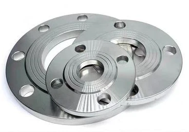
Figure 1 shows the flange bearing, where flange accuracy and tolerance are key to clearance, self-alignment, and overall performance.
Flange surface and hole accuracy directly affect bearing life, performance, centering, and deflection torque.
And the centering ability, deflection torque and the size of the clearance directly affect the realization of the function of the assembly.
To meet functional requirements and improve accuracy, designers set stricter machining standards for the flange.

Flange material and structure analysis
Figure 2 shows a 17-4PH flange with high corrosion resistance and excellent machinability for high-quality applications.
The flange has a 97 mm maximum diameter, 1.4 mm minimum wall, 0.003 mm flatness, and Ra 0.63 μm surface roughness.
The flange and bearing outer ring require SφC 0 –0.007 mm, Ra 0.2 μm, φ(A ± 0.02) mm mutual reference, and ≤0.02 mm coaxiality for the locating hole.
With large cuts, maintaining size accuracy and tolerance is challenging, so cutting parameters are key to flatness and surface finish.
Flange parts are large, thin-walled, high-precision, and easily deformed, making processing difficult with low yield.

Analysis of factors affecting flange processing
Product’s own deformation
Flange parts billet for 17-4PH martensitic precipitation hardening stainless steel, the processing process requires cutting to remove more raw materials.
After turning, changes in internal structure and residual stress can cause severe deformation, poor dimensional accuracy, and scrap.
During machining, 17-4PH’s low stiffness makes improper clamping deform the workpiece, worsening with cutting and risking scrap.
Vibration in the turning process
Flange for the aerospace field of high-precision thin-walled parts, material removal in the process of processing more, while the surface quality requirements are extremely high.
The stiffness of the thin-walled product itself is in constant flux as the turning process continues.
Turning and milling vibrations deform thin-walled parts, reducing geometric accuracy and performance.
Flange machining accuracy assurance methods
Selection of process route
The flange is a high-precision, thin-walled, symmetric ring with mounting holes requiring high geometric accuracy, flatness, and surface finish.
Traditional radial clamping can push the thin 1.4 mm flange walls out of tolerance.
Using annealed bar stock, roughing with OD/ID clamping, followed by heat treatment and semi/finishing, ensures part accuracy after stress relief.
Axial clamping with magnetic cups and pins reduces radial deformation and improves flange accuracy.
Flange machining: roughing → stress relief → double-face grinding → tempering → fine turning → milling → thermal cycling → wire cutting → surface treatment → inspection.
Measures taken in machining method
Flange machining analyzes shape, material, and structure to identify influencing factors and apply targeted process controls.
- Magnetic cups and radial pins reduce flange deformation, improving machining accuracy and coaxiality.
Figures 4 and 5 show finite element strain and stress analysis under current clamping and high-speed rotation.
Analysis shows ~0.1 μm displacement and 0.74 MPa stress, indicating minimal clamping impact on accuracy.


- The product, made of 17-4PH stainless steel, undergoes hard turning (32–34 HRC) after quenching to ensure good cutting performance.
This improves surface quality and machining accuracy, enabling grinding to replace turning.
Operators use high-precision hard turning equipment with an adjustable magnetic suction cup (controlled by coil current).

Measures taken in the machining process
- Operators precision-turn the flange, process pin holes and notches, then remove the 75° outer ring by wire cutting to avoid vibration and tool breakage.
Roughing followed by quenching and tempering ensures efficiency, accuracy, and improves hard turning surface quality.
Engineers set the hard turning allowance to 0.5–1 mm based on deformation and efficiency from multiple process tests.
Finishing the inner sphere SφC requires Ra 0.2 μm, roundness 0.002 mm, and 0.2–0.8 mm cutting allowance. The flange state is shown in Figure 6.

- Rough machining of flange parts generates residual stress, affecting material yield strength and subsequent machining accuracy.
Stress relief after roughing, followed by cold–hot cycling after finishing, stabilizes the material and prevents residual stress damage.
Cold–hot cycling relieves stress, strengthens the flange, improves yield, and ensures accuracy and quality.
Fig. 7 and Fig. 8 show the organization composition of the material before and after stress removal under the same magnification.


- Machining accuracy and quality of thin-walled parts mainly depend on cutting vibration intensity.
By increasing the auxiliary support in the machining process, the workpiece stiffness is increased and the cutting force is more balanced.
Suppressing machining vibration is an important method to ensure machining quality.
During machining, increasing the suction cup’s electromagnetic force presses the flange’s large end face closer, improving overall stiffness.
After adjustment and trial cuts, non-magnetic tools with abundant cutting fluid significantly improve flange machining accuracy.
Conclusion
This paper presents flange processing methods and improvement measures based on part materials, structure, and machining factors.
Improving clamping, operators mount the workpiece with a magnetic suction cup and axial pin to avoid radial force.
Trial cutting determines the optimal cutting dosage, minimizing workpiece deformation from clamping and cutting stress.
Heat treatment with roughing and tempering boosts hardness and stiffness, improving surface and machining quality in high-speed hard turning.
Adjusting cutting allowance reasonably allocates size tolerance to ensure part machining accuracy.
Increasing the magnetic coil strengthens workpiece adsorption and rigidity, reducing vibration-induced part errors.
These methods also apply to similar flange materials (9Cr18, 9Cr18Mo, 2Cr13), providing a practical reference.
To prevent deformation from clamping force, use a magnetic suction cup with a positioning pin.
Stress-relief annealing and hot–cold cycle heat treatment reduce part deformation from heavy cutting.
Operators perform turning and contour cutting on irregular or shaped flanges to avoid vibration and tool damage, ensuring machining accuracy.

