What Is Sheet Metal Beading?
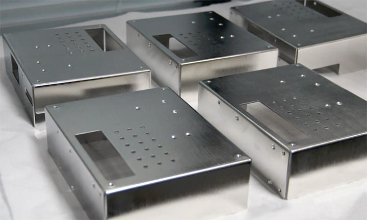
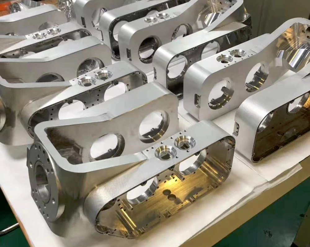
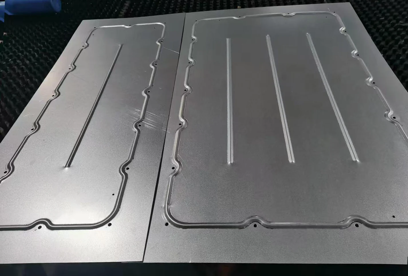
Sheet metal beading is a metal forming process that creates raised or recessed ribs on sheet metal parts to improve rigidity, strength, and dimensional stability. It is widely used in automotive, aerospace, industrial equipment, HVAC, and electronics manufacturing.
How Can Sheet Metal Beading Accuracy Be Improved?
Sheet metal beading accuracy can be improved through optimized blank design, 3D simulation, laser vision inspection, CNC compensation, and dimensional verification. These technologies help reduce deformation, improve consistency, minimize material waste, and achieve higher forming precision.
Key Takeaways
- Sheet metal beading improves strength without increasing material thickness.
- Traditional beading processes often result in dimensional variation and material waste.
- 3D simulation helps predict shrinkage and deformation before production.
- Laser inspection provides accurate measurement of edge deformation.
- CNC compensation improves forming accuracy and reduces secondary trimming.
- Modern beading processes increase material utilization and manufacturing efficiency.
Why Is Sheet Metal Beading Important?

Sheet metal parts often need to withstand mechanical stress, vibration, and repeated loading. A flat sheet can easily bend or lose shape, especially when the thickness is limited.
Beading creates additional structural support by changing the geometry of the sheet rather than adding extra material.
Key benefits include:
| Benefit | Description |
|---|---|
| Higher Strength | Improves rigidity without increasing thickness |
| Weight Reduction | Maintains strength while using less material |
| Better Durability | Reduces deformation under pressure |
| Vibration Control | Helps reduce noise and panel movement |
| Cost Efficiency | Reduces material usage compared with thicker sheets |
Common Applications of Sheet Metal Beading
Sheet metal beading is widely used in industries where precision, strength, and lightweight construction are important.
Automotive Components
In automotive manufacturing, beading is used to strengthen body and structural panels while maintaining weight efficiency.
Common applications:
- Vehicle doors
- Hood panels
- Chassis components
- Interior metal structures
- Protective covers
Beaded designs help automotive parts maintain shape under vibration and mechanical stress.
Aerospace Components
Aerospace manufacturers use sheet metal beading to create lightweight structures with improved stiffness.
Common applications:
- Aircraft panels
- Lightweight structural supports
- Interior aircraft components
- Equipment brackets
The process helps reduce weight while maintaining required strength standards.
Industrial Equipment
Industrial machinery requires metal panels that can resist vibration and repeated operation.
Common applications:
- Machine enclosures
- Equipment covers
- Protective guards
- Structural panels
Beading improves rigidity and reduces deformation during long-term operation.
Electronics and Electrical Equipment
Electronic equipment often requires thin metal housings that remain strong and stable.
Common applications:
- Electrical cabinets
- Control panels
- Server enclosures
- Instrument housings
Beading provides additional stiffness while keeping enclosure designs compact.
Sheet Metal Beading Design Guidelines
Correct bead design is essential for achieving strength and dimensional accuracy.
| Design Factor | Recommended Guideline |
|---|---|
| Bead Depth | 1–3× material thickness |
| Bead Width | 4–8× material thickness |
| Minimum Edge Distance | Around 2× material thickness |
| Material Selection | Aluminum, stainless steel, carbon steel |
| Bead Spacing | Maintain uniform spacing for consistent forming |
Poor bead placement can cause uneven deformation, cracking, or dimensional variation during forming.
Typical Sheet Metal Beading Tolerances
Tolerance requirements depend on material, thickness, tooling condition, and manufacturing method.
Typical achievable ranges:
| Feature | Typical Tolerance |
|---|---|
| Bead Height | ±0.2 mm |
| Bead Width | ±0.3 mm |
| Overall Part Dimension | ±0.5 mm |
For high-precision applications, manufacturers often use measurement systems and compensation methods to improve repeatability.
Best Materials for Sheet Metal Beading
Different materials behave differently during forming. Material selection affects strength, surface quality, and dimensional stability.
| Material | Advantages | Common Applications |
|---|---|---|
| Aluminum | Lightweight, corrosion resistant | Aerospace, automotive |
| Stainless Steel | High strength, corrosion resistance | Medical, industrial equipment |
| Carbon Steel | Strong and economical | Machinery, structures |
| Galvanized Steel | Corrosion protection | Enclosures, outdoor equipment |
Factors Affecting Sheet Metal Beading Cost
The final cost depends on several manufacturing factors:
Material Type
Higher-performance materials may require specialized tooling and processing.
Sheet Thickness
Thicker materials generally require more forming force.
Production Volume
Large production runs reduce per-part costs through optimized setup.
Tooling Requirements
Custom dies or forming tools increase initial investment.
Part Complexity
Complex bead patterns require more engineering and inspection.
Secondary Operations
Additional cutting, finishing, or inspection steps affect production cost.
Analysis of the Current State of Sheet Metal Beading Processes
Traditional Sheet Metal Beading Process Flow
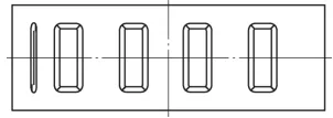
For parts like the one shown in Figure 1, the traditional sheet metal beading process typically involves the following steps:
First, raw material is cut into rough blanks using a shearing machine. Then, stamping equipment and specialized dies bead the sheet metal.
After beading, a blanking die or shearing machine performs secondary cutting to remove excess material around the edges.
Some processes also require manual or robotic assistance for loading/unloading to facilitate the transition between forming and trimming operations.
In the production of sheet metal parts with multiple specifications and dimensions, this process features high repetition, strong mold dependency, and requires significant manual handling and positioning during process transitions.
Analysis of Existing Issues
1) Low raw material utilization rate: The use of fixed molds for forming and blanking prevents effective utilization of peripheral scrap, resulting in significant waste.
2) Poor mold adaptability: Any changes to product dimensions necessitate complete mold redesign rather than adjustment, increasing production costs and lead times.
3) Existing processes involve extensive secondary handling and loading/unloading operations.
Whether performed manually or by robotic arms, these steps consume substantial labor and resources, further extending production cycles and reducing manufacturing efficiency.
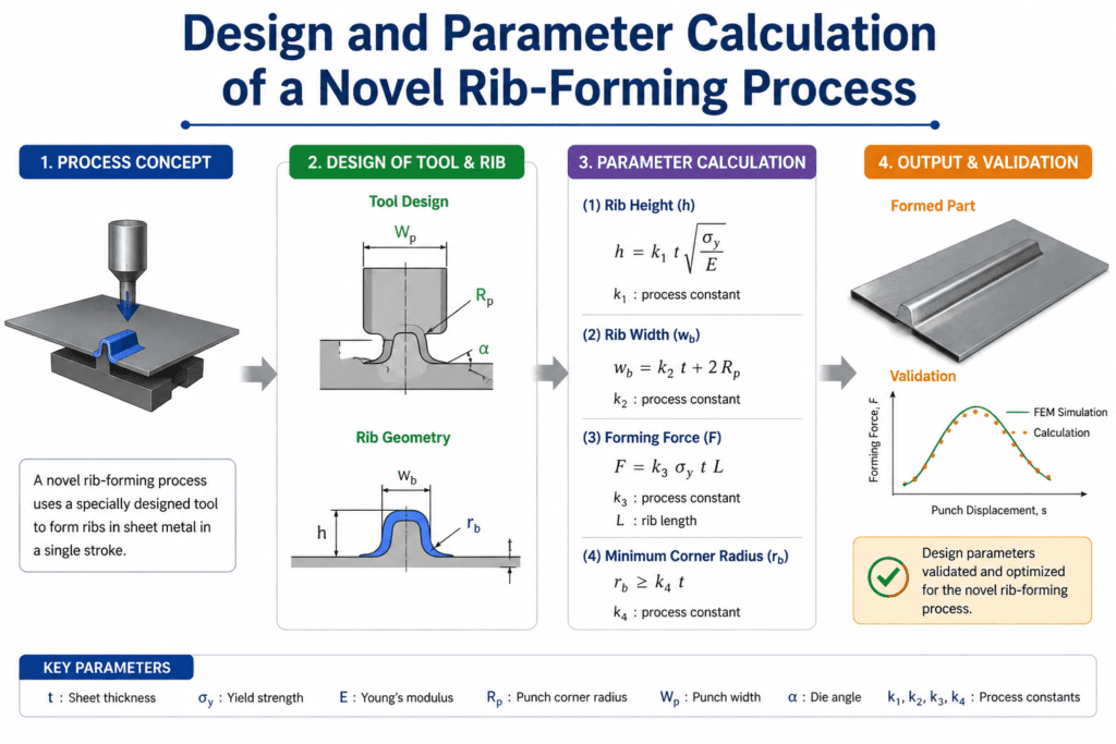
Design and Parameter Calculation of a Novel Rib-Forming Process
Process Flow Overview
To enhance the efficiency and precision of sheet metal beading processing, this paper proposes an innovative manufacturing process integrating 3D simulation analysis, laser vision inspection, and parameter compensation: 3D Simulation Analysis → Laser Inspection → Compensated Cutting → Beading Verification → Mass Production.
(1) 3D Simulation Analysis
By establishing a digital model of the beaded workpiece, combined with material property parameters and forming structure requirements, this step predicts dimensional shrinkage patterns and deformation trends post-beading to determine optimal blank development dimensions.
(2) Laser Vision Inspection
Non-contact measurement of flanged samples using a 3D laser scanner captures point cloud data and generates edge deformation curves, yielding critical actual shrinkage values such as ΔL and ΔW.
(3) Compensated Cutting
The system symmetrically expands the deformation data outward from the workpiece center.
Laser inspection data informs cutting pattern compensation design, enabling CNC programming and laser cutting to achieve the final shape.
(4) Bead Forming Validation
Subject the compensated blank to forming trials to verify dimensional accuracy, ensuring single-pass forming without secondary trimming.
(5) Mass Production
Initiate batch processing upon parameter stabilization and dimensional compliance, implementing process sampling to guarantee product quality.
This workflow significantly enhances material utilization, dimensional consistency, and process flexibility.
Theoretical Parameter Calculation
(1) Constant Metal Volume Method
During sheet metal beading, although parts undergo significant dimensional shrinkage and deformation after beading, their metal volume remains constant.
Therefore, engineers derive the blank volume formula from the relationship between metal mass and density: V = m/ρ.
Here, V represents the blank volume, m denotes the sheet metal part’s mass, and r is the material density.
This method serves as the foundation for dimensional unfolding calculations and is applicable to common homogeneous materials like steel and aluminum alloys.
By controlling the initial blank mass and material type, engineers can deduce the theoretical unfolding dimensions, providing accurate references for subsequent area and length and width calculations.
(2) Unfolded Area and Dimension Formulas
After determining the blank volume V and material thickness t, the unfolded blank area S can be derived as S = V/t.
Based on the workpiece geometry, if designed as a rectangular or square blank, its length L and width W satisfy S = LW.
If one dimension is known, engineers can calculate the other using L = S / W or W = S / L.
These dimension calculations provide the theoretical basis for preliminary blank cutting.
By establishing mathematical models based on 3D simulations and structural dimension data, engineers can achieve automated parameter extraction and process compensation design, laying the foundation for subsequent laser compensation pattern construction.
(3) Setting and Selection of Width Allowance Coefficient
In actual bead forming operations, due to the nonlinear shrinkage effect of sheet metal during forming, theoretical developed dimensions often fall short of final forming requirements.
Therefore, an appropriate width allowance coefficient K must be set to correct the calculated length and width. The correction formula is: L = KL_(theory), W = KW_(theory).
This coefficient typically ranges from 1.1 to 1.3, with specific values determined based on bead depth, material plasticity, die structure, and process experience.
A K value that is too small may result in insufficient blank edges, causing dimensions to fail post-beading; conversely, an excessively large K value increases material waste.
Therefore, after obtaining a reasonable shrinkage ratio through preliminary 3D simulation and prototype testing, the K value can be accurately set.
This enhances the adaptability of blank design and improves post-processing forming accuracy, effectively avoiding traditional trimming or rework operations.
CNC Laser Pre-Compensation Strategy
Using a laser 3D vision inspection system, capture deformation data of the edge segments on the bead sample.
Extract the actual shrinkage values in the length and width directions, denoted as ΔL and ΔW respectively.
Engineers use the workpiece center point as the symmetry reference and evenly distribute the contraction amounts across the four sides of quadrilateral ABCD.
Compensation of ΔL/2 and ΔW/2 is applied outward, redefining the coordinates of the four corner points to form compensation points A’, B’, C’, and D’.
Engineers apply mirror symmetry processing to these compensation corners, combined with the edge curves obtained from laser scanning, to generate a laser cutting pattern that incorporates actual contraction compensation.
After programming and importing this pattern into CNC laser equipment, direct cutting proceeds.
This ensures the blank dimensions meet assembly tolerance requirements without secondary trimming after beading, significantly enhancing manufacturing precision and production efficiency.
3D Visual Inspection and Point Cloud Model Construction
Components of a 3D Laser Scanning System
A 3D laser vision inspection system primarily consists of a laser scanner, data processing host, control software, and display terminal.
The scanner performs non-contact scanning of workpiece surfaces by emitting laser beams to capture edge point cloud data, offering high precision and efficiency.
The system provides real-time feedback on workpiece contour changes, making it particularly suitable for precision inspection of edge deformation in sheet metal press-formed parts.
When integrated with specialized processing software, it generates complete 3D models, delivering accurate data support for subsequent compensation analysis and laser cutting operations.
Point Cloud Data Acquisition and Processing Workflow
Point cloud data obtained from laser scanning requires processing to extract meaningful information.
First, noise removal and data registration are performed to ensure consistent stitching of multi-angle scan data.
Engineers then extract edge curve features and conduct curvature analysis on the edges.
Finally, a 3D contour model is generated, accurately reflecting the shrinkage deformation caused by ribs.
This provides authentic geometric basis for parameter compensation design, significantly enhancing data reliability and the precision of compensation strategies.
Edge Shrinkage Data Extraction and Model Feedback Mechanism
Based on the 3D point cloud model, the actual deformation curves of the four edges of the beaded part are extracted and compared with the theoretical design dimensions to calculate the shrinkage values ΔL in the length direction and ΔW in the width direction.
The system sets compensation values based on the shrinkage data and feeds them back to the blanking pattern generation module, enabling pattern correction prior to processing.
This closed-loop mechanism effectively enhances the first-pass forming accuracy of the stiffener, eliminates secondary trimming operations, and boosts the intelligence and flexibility of the manufacturing process.
Conclusion
This paper addresses dimensional accuracy control in the forming process of sheet metal stiffener components by proposing a novel manufacturing method centered on 3D modeling analysis, laser vision inspection, and pre-compensated laser cutting.
Through theoretical parameter calculations and practical process validation, it achieves precise compensation of blank dimensions and one-step stiffener forming, significantly reducing material waste and labor input.
Research indicates this method offers strong versatility, high flexibility, and suitability for multi-variety small-batch production, providing an effective technical pathway for the intelligent upgrade of sheet metal manufacturing

Solomon Yang is a manufacturing industry professional with extensive experience in electronic, mechanical, and industrial component manufacturing. Having held various positions in American and Taiwanese manufacturing companies, he has developed a comprehensive understanding of manufacturing processes, production management, quality control, and global supply chain operations.
With expertise in business development, sales operations, international trade, customer relationship management, and engineering project support, Solomon bridges technical knowledge with commercial strategy to deliver innovative and cost-effective manufacturing solutions. He is passionate about advanced manufacturing technologies, process improvement, and continuous professional growth, with a strong commitment to creating value for customers and partners worldwide.