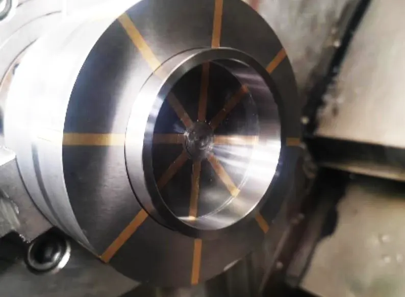
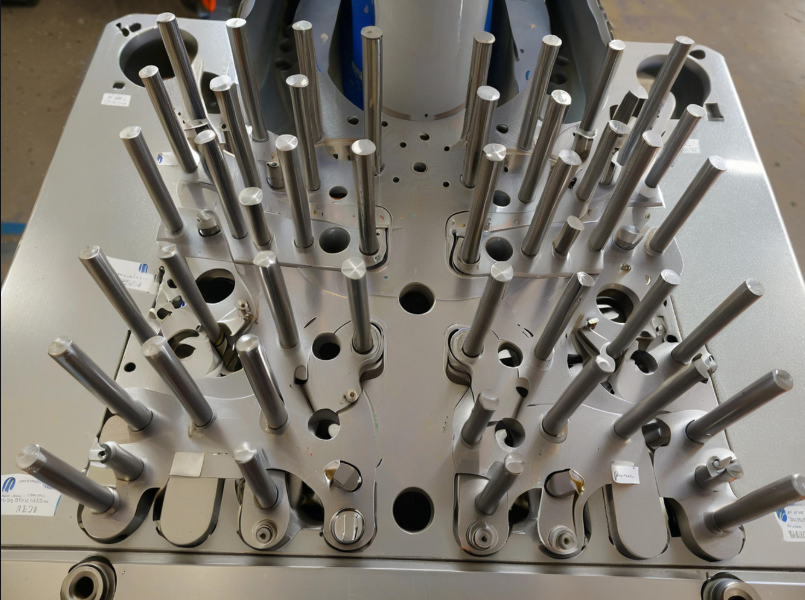
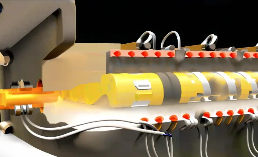
A shield machine is a type of engineering machinery specifically used for tunnel excavation. Its sealing ring components, along with other auxiliary seals (such as polyurethane retaining rings and nitrile rubber sealing rings), form a complete sealing system.
This sealing system ensures that the earth silo of the shield machine remains free from slagging soil and groundwater.
It also provides sealing and lubrication for the main drive, helping to ensure the service life of the main bearing.
There are rings in the main drive and shield body of the shield machine, among which the main drive has the most specifications and types of rings.
The rings in the main drive are mainly divided into sealing rings, isolation rings, compression rings, labyrinth rings, connecting rings and so on according to their functions.
The use of metal rings can maximize the load-bearing capacity of the entire main drive sealing system.
This is one of the key factors for ensuring the normal drilling operation of large-diameter shield machines, and even super-large-diameter shield machines.
Role of Metal Rings in Load-Bearing Capacity
Taking the sealing rings in the main drive of a large-diameter shield machine as an example, the diameter-to-thickness ratio of each ring is greater than 150, which is an extremely typical thin-walled ring.
During the machining process, the workpiece clamping, positioning, transfer and selection of process routes have a great impact on the deformation of the workpiece and machining accuracy.
Especially in the processing of large-diameter thin-walled rings, the dimensional tolerance and deformation of the workpiece is more difficult to control, which directly affects the assembly of the main drive.
In this paper, a tunnel boring machine sealing ring is used as an example. The machining process of large-diameter thin-walled ring parts is analyzed.
A set of economic and feasible machining programs is proposed.
These programs are designed to meet the assembly requirements of the parts while reducing production costs.
Parts model
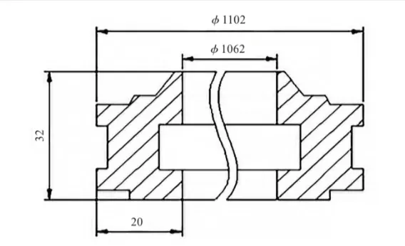
To a tunnel boring machine in the thin-walled ring A as an example, the workpiece material for the 42CrMo.
The workpiece outer diameter size of 1102mm, inner diameter size of 1062mm, total height of 32mm, and its cross-section sketch is shown in Figure 1.
Machining process of large diameter thin-walled rings
The difficulty in machining large diameter thin-walled rings lies in the clamping alignment and machining stress control, especially when it is realized with an efficient and low-cost solution.
It is very challenging to realize the machining of large-diameter or even super-large-diameter thin-walled rings with a high degree of generalization and a low-cost solution.
In this paper, high quality machining of thin-walled rings is achieved by controlling the clamping, centering, and machining deformation of the rings.
Take the machining of thin-walled ring A in Fig. 1 as an example.
Ring A has a tongue-like profile protruding from one end, which is unfavorable for machining by ordinary clamping, and if special tooling is designed and produced, it involves too many specifications.
In the main drive of a shield machine, there are usually 1 to 5 rings with similar structure and the same inner and outer diameters as ring A.
The number of thin-walled rings of this type depends on the geological conditions of the shield machine.
Based on the mentioned problem and the shape of the part, a multiple-piece unloading method is adopted.
In this method, several thin-walled rings with the same inner and outer diameters are rolled and unloaded together.
Additionally, one extra piece is added on top of the required number of rings.
The height of the blank size for this extra ring should preferably be twice the thickness of the ring..
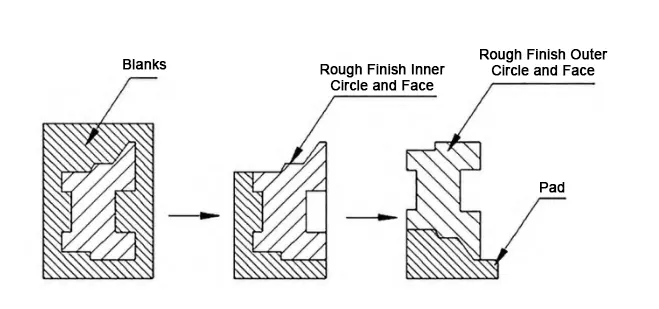
As shown in Figure 2, after the completion of material processing, the main steps are as follows:
(1) Safe Turning and Manual Separation Process for Workpieces
Separately from the inner circle and the outer circle surface turning off the workpiece; turning off, try not to directly turn the workpiece off, in the radial direction there is a 3mm residual, stop turning, manual separation of the workpiece.
According to the same method of processing other ring parts, the remaining blank can be used as spare parts or do imitation workpiece, after processing for padding the tongue of thin-walled ring parts.
(2) Clamping and Face Machining Instructions for Ring A
Clean up the worktable, turn the ring A, at least 8 evenly distributed pressure plate will be clamped on the worktable, find the workpiece outer circle, the car end face all see flat (the ring is cut from blanks, the two end surfaces have seen the light).
(3) Inner Ring Groove Turning with 2mm Radial Allowance
Press the workpiece from the outer circle, rough the inner circle to the size, turn the inner ring groove, leaving a 2mm margin of radius;
Rough turning end face step (Figure 3), turning beveled, leaving 2mm margin; rough turning inner circle to size, leaving 2mm margin.
(4) Reclamping and Final Machining of Aged Workpieces
After aging treatment of the workpiece, reclamp and straighten the workpiece on the machine according to the above steps. Semi-finish turning, finish turning end face to size;
Semi-finish turning, finish turning step end face and beveled face to size; pay attention to ensure the surface roughness requirements; rough and finish turning inner circle and ring groove to size.
(5) Hole Processing and Beveled Edge Milling for Ring A
Ring A has threaded holes or light holes in the circumferential direction. Process the holes according to the requirements of the drawing.
Use a 10mm diameter milling cutter to mill the beveled edge of the step. Then drill the holes.
(6) Flipping and Precision Machining of Ring Workpiece with Custom Tooling
Turn over the workpiece using the special turning tooling designed for ring pieces. Place the workpiece on an equal-height block, which can be made from available material as tire pads.
Correct the inner round surface of the workpiece. Press the workpiece from the outside.
Rough and finish turn the end face to the required thickness size. Rough and finish turn the tongue, step, and bevel to the specified dimensions.
(7) Turning and Tolerance Control of Thin-Walled Rings Using Custom Jigs
Press the workpiece from the inner side, and then loosen the outer pressure plate. First, press one side of the workpiece, and then loosen the other side.
Proceed with semi-finish turning. Next, finish turning the outer circle to the specified size.
Then, finish turn the outer ring groove to its final dimension. Finally, perform roughing and finishing turning on the tongue to reach the required size.
It is necessary to pay close attention to the machining process to ensure that the shape and position tolerance requirements are met.
During the turning process, the amount of tool engagement and feed should be minimized.
This helps to prevent deformation of the workpiece. Machining process schematic shown in Figure 3.
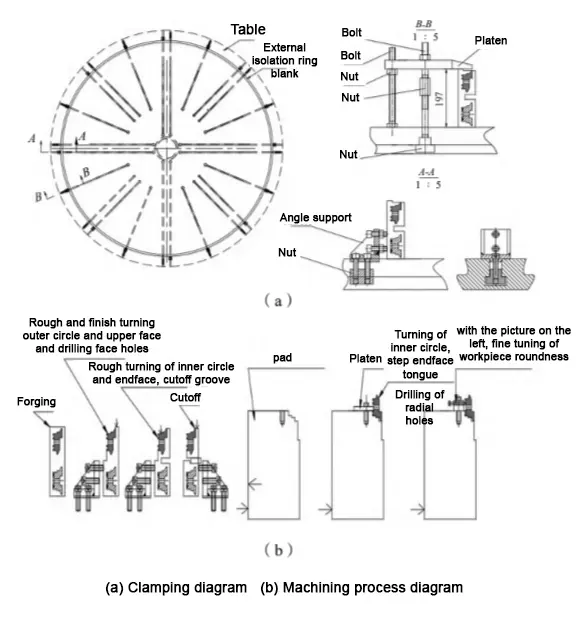
Without adding large-scale special equipment, the clamping and centering of thin-walled rings are realized by designing small clamping jigs and tire pads.
In the machining process, roughing and finishing are carried out separately.
The workpiece is loosened and undergoes aging treatment between the roughing and finishing stages. This process helps release the machining stress accumulated during roughing.
For parts with particularly high precision requirements, vibration aging is used to remove the residual stress more effectively.
Principles for Sequencing Machining Operations Based on Workpiece Size
Combined with the characteristics of the external dimensions of the workpiece, adjust the machining sequence of the part shape, the basic principles are:
(1) a clamping as much as possible according to the drawings required size processing in place.
Reduce the number of clamping can be greatly avoided clamping reference does not coincide with the processing errors caused by.
(2) for the coaxiality, perpendicularity requirements of the size, as far as possible in the same clamping completed.
In the process of a tool in the formation of the external dimensions, can maximize its coaxiality, perpendicularity.
(3) Easy to clamp the end face priority for finishing.
Drawings on the contour of the morphology of the more moderate changes in the end of the priority for finishing, easy to turn over as another end of the stable finishing benchmark.
According to the characteristics of the ring’s shape and the classification of materials, rings with similar specifications are processed using the same machining pads. An example of such field machining cases is shown in Figure 4.
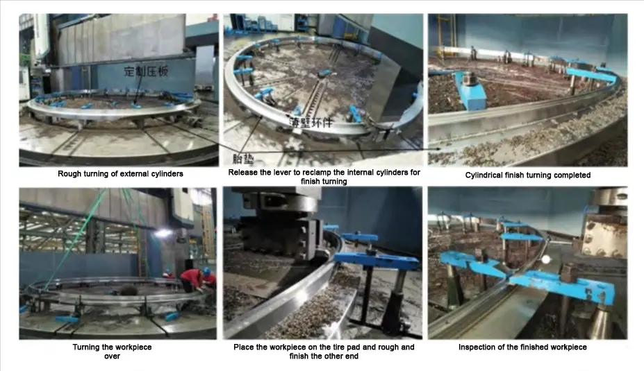
Stress relief program for large diameter thin-walled rings
After rough machining is completed, the parts continue to vibration aging or natural aging treatment, stress relief annealing when conditions allow, so as to achieve the purpose of stabilizing the size.
After aging, the part is then finish machined.
In actual on-site machining, the effect of stress relief annealing is much greater than that of vibratory aging. Vibratory aging was developed from the “hammer relaxation method” (percussion aging).
During the vibration aging process, periodic dynamic stress is applied to the component.
This dynamic stress is superimposed on the residual stress already present in the material.
When the combined stress reaches the material’s yield stress, the component begins to resonate.
This resonance leads to localized plastic deformation within the component.
This plastic deformation usually first appears in the region with the largest residual stress.
It prompts the relaxation and release of residual stress in that area.
As a result, the size of the workpiece is stabilized, achieving the goal of eliminating residual stress.
However, the residual stresses removed by vibration aging are limited. For thin-walled ring parts, the use of stress relief annealing has a good effect on stabilizing the size of the parts.
At the same time, Hauckner ultrasonic impact is applied to the ring before finishing.
This high-frequency vibration impact helps to release the residual stresses present in the workpiece.
Additionally, it transforms the tensile stress state on the workpiece surface into a compressive stress state.
Large diameter thin-walled ring turning program
In practice, the workpiece with good stiffness is usually transported directly by traveling car and turned in the air.
Tunneling equipment in the sealing ring diameter of 3 ~ 7m, diameter to thickness ratio are greater than 150 and has a complex structure.
They need to be turned over frequently during processing, and the parts themselves have poor rigidity. The traditional turning method is very easy to cause deformation of the workpiece.
The existing lifting tooling only has the function of lifting, and cannot realize the function of turning and long-distance transportation at the same time.
For the flat lifting of thin-walled rings, a sling can be used. However, when it is necessary to turn the workpiece over, auxiliary tooling must be employed.
Otherwise, the workpiece may become deformed due to the stresses introduced during the turning-over process.
Workpiece storage
At the same time, it is also necessary to consider the storage of the workpiece after processing.
For the turning over of finished thin-walled rings, large-diameter thin-walled rings are generally fixed using ring support plates.
The turning over, horizontal lifting, and vertical lifting of the thin-walled rings are achieved by using lifting lugs positioned at different locations.
This method effectively avoids deformation of the thin-walled rings, which can be caused by uneven force during the lifting process (Fig. 5).
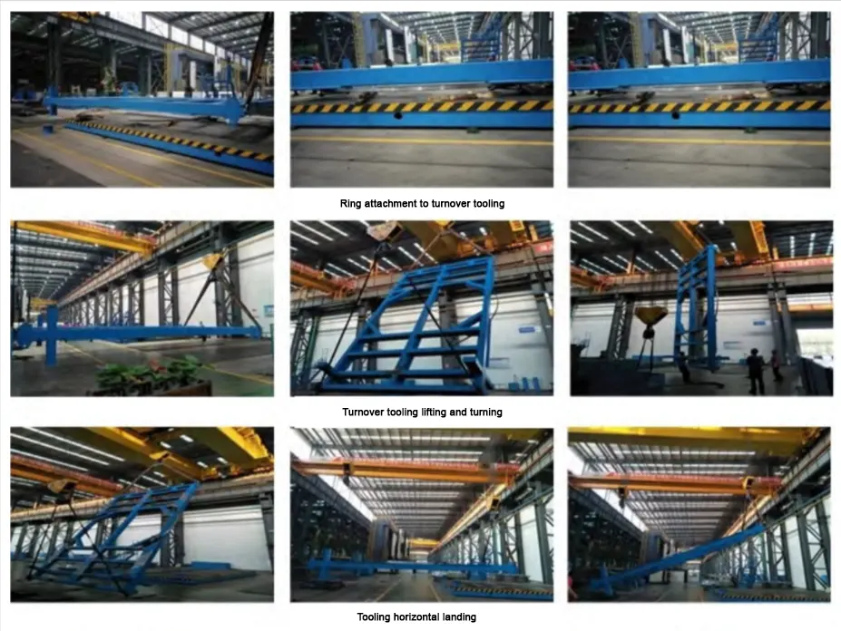
The reasonable design reduces the number of fixtures for turning over of large diameter thin-walled rings and facilitates the long-distance transportation of the rings.
Conclusion
In this paper, the processing of large-diameter shield seal thin-walled parts—which are prone to deformation—is studied in detail.
Optimization and improvement are carried out from several aspects, including clamping, positioning, transfer, and the selection of process routes.
Additionally, the design of specialized jigs, fixtures, and turnover tools is addressed to enhance machining stability and precision.
After processing with the processing program proposed in this paper, the processing size of the seal ring meets the assembly requirements, and there is no repair matters.
From the point of view of the whole life cycle of the product, the use of this program can realize the low-cost processing of parts and improve the processing effic

