
Flange for short, just a general term, usually refers to a disk-like metal body around the perimeter of a few fixed holes for connecting other things.
This part is widely used in machinery, so the appearance is also strange, as long as the like is called flange, its name is derived from the English flange.
In this paper, a set of drilling mold is designed for φ6 mm inclined holes which are difficult to be processed.
Drilling machine fixture is used for a variety of drilling machines and some boring machines, combined machine tools on the fixture, referred to as drilling mold ( boring mold ).
Its main role is to ensure the positional accuracy of the machined hole.
Drilling fixture mainly consists of positioning elements, clamping devices, drilling template, drilling set, clamping specific components.
Parts diagram analysis
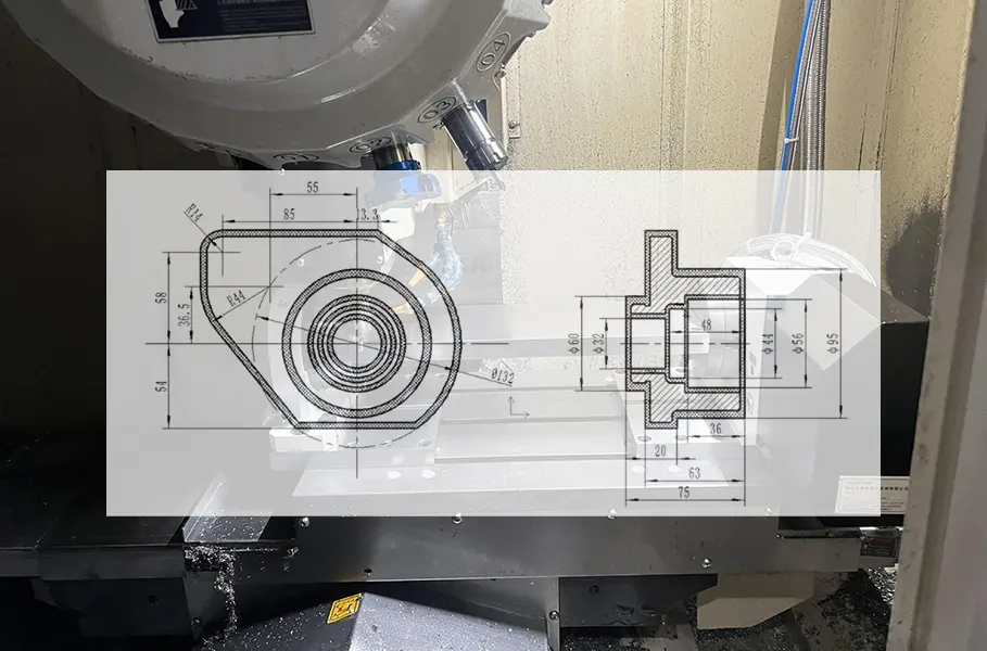
To be processed flange parts of the two-dimensional engineering diagram shown in Figure 1, three-dimensional diagram shown in Figure 2.
The workpiece material is HT200 that has good cutting performance.
It is very suitable for CNC machining. The batch size is 4,000 pieces.
This production run is classified as high-volume. This part needs to process more parts.
(1) Machining Accuracy Requirements
The machining accuracy of the outer circle, φ50 h6 mm, is 0.016 mm. The inner contour’s accuracy , φ62 K7 mm, is 0.03 mm.
The size requirements for all other dimensions are not stringent.
(2) Surface Roughness Requirements
The roughness of the outer contour sizes is Ra 1.6 μm to Ra 3.2 μm. Inner roughness contour sizes is Ra 1.6 μm to Ra 6.3 μm.
The 7 × φ9 mm holes’ roughness is Ra 12.5 μm. All other surfaces have a roughness of Ra 6.3 μm.
(3) Form and Position Tolerances
The runout tolerance of the center axis of the φ62 K7 mm hole, referenced to datum A, is 0.02 mm.
Its tolerance of the 38 mm 0 +0.2 inner-contour end face, referenced to datum A, is 0.02 mm.
The tolerance of datum B, when referenced to datum A, is 0.02 mm.
The positional tolerance of the center axis of the 7 × φ9 mm hole, referenced to datums B and A, is 0.2 mm.


Figure 2 three dimensional drawing of the part
Blank design
The material of the part blank is HT200 gray cast iron, and the processing method is casting.
Casting generally does not apply pressure, the strength of the equipment and mold requirements are not high, the size of the product is less restrictive.
Therefore, the required production input is lower. This method can yield large-scale parts with excellent performance.
However, the production cycle is longer. In traditional casting, the molded parts must still undergo machining.
This blank in the casting molding must also be aging treatment before machining. The casting blank of the part is shown in Figure 3, the blank size is:
165 mm × 126 mm × 75 mm (bore φ32 mm).

Process analysis
Machining Process Card
The machining process card uses each process as a unit. It provides a concise listing of all parts processed along the route.
This list includes blank manufacturing, machining operations, heat treatment, and other relevant steps.
It is the basis for the development of other process documents, as well as production preparation, scheduling operation plan and organization of production.
In this card, the process description is not specific enough. Therefore, it generally does not directly guide the workers’ operations.
Instead, it is used more for production management purposes.
But in a single piece of small batch production, because usually do not prepare other more detailed process documents, and this card to guide production.
This part of the machining process is detailed in Table 1 machining process card.

CNC Machining Processes
The machining content of process 3 (turning process) is shown in Table 2 CNC machining process card.
This process uses CKA6140 CNC lathe, program number O1, O2, using three-jaw chuck to clamp the workpiece.

The processing content of process 5 (milling process) is shown in Table 3 CNC machining process card.
This process uses VDL850A machining center, the program number is O1, using three-jaw chuck to clamp the workpiece.

CNC machining tools
The contents of the tools for process 3 (turning process) are shown in Table 4 CNC machining tool card.

The tool content of process 5 (milling process) is shown in Table 5 CNC machining tool card.

Feed roadmap
The feed roadmap of process 3 (turning process) is shown in Fig. 4.
")
The feed route map of process 5 (milling process) is shown in Fig. 5.
")
Fixture design
The φ6 mm diagonal hole in Process 8 is difficult to machine. There are many ways to machine the slanting hole.
A keyway end mill with the same or slightly larger diameter can be used to mill a shallow hole, and then switch to an ordinary drill to drill the hole;
When the slant is very small, the drill can be ground to a special double-point-angle geometry.
In this configuration, the center portion’s point angle is made slightly smaller.
The outer edge’s point angle is made slightly larger. The exact values of these angles depend on the specific workpiece.
The above two commonly used methods do not take into account the structure at the bottom of the inclined hole.
For a through-hole like this one, when the drill bit exits the hole, the forces on both sides of the bit become uneven.
If there is no special drilling sleeve to support the drill bit, it can break easily.
Considering that the required roughness of the φ6 mm inclined hole is Ra 6.3 μm, the hole must be drilled twice.
To facilitate this, a quick-change special drilling sleeve structure was designed. See Fig. 6 for details.
The distance between the bottom bevel of the quick-change special drilling sleeve and the bevel of the workpiece is 0–0.1 mm.
This very short gap ensures better rigidity of the tool.
In this paper, a set of special fixture is designed for this difficult to machine φ6 mm inclined hole, and its assembly diagram is shown in Figure 6.
The components in the figure are:
- 1 – base plate;
- 2 – clamping specific;
- 3 – hinged shaft;
- 4 – reversible drilling template;
- 5 – hexagon socket head cap screws;
- 6 – flat washers;
- 7 – drilling bushing bushings;
- 8 – interchangeable drilling bushings;
- 9 – locking screws;
- 10 – cotter washers;
- 11 – hexagonal nut;
- 12 – fixed rhombic pins;
- 13 – cylindrical pins;
- 14 – small diameter bolts;
- 15 – fixed cylindrical pins;
- 16 – cotter pins.

The three-dimensional structure of the whole set of special fixture for drilling die for inclined hole is shown in Fig. 7.
The workpiece is positioned by two pins on one side.
The base plate restricts three degrees of freedom on the inclined surface of the clamping body:
- Z-axis movement;
- X-axis rotation;
- Y-axis rotation;
Together, the cylindrical pin and the diamond-shaped pin restrict the remaining three degrees of freedom:
- Z-axis rotation;
- X-axis movement;
- Y-axis movement;
This arrangement achieves complete positioning of the workpiece.
Cylindrical pins are manually inserted and removed to locate the workpiece, and are inserted and removed once every time the workpiece is mounted.
The clamping method adopts the locking method of nut and open washer, which has a compact structure and is easy to disassemble.
In the process of machining, in order to ensure the stability of the drilling template.
It is necessary to add a locking bolt, the position and structure of which are shown in Figure 7.

Calculation of positioning error
Positioning error refers to the error caused by the inconsistent position of a batch of workpieces in the fixture.
The position inconsistency is caused by the manufacturing error of the localization vice;
Datum Displacement and Misalignment Errors
The position inconsistency caused by the non-coincidence of the process datum and the positioning datum are all positioning errors, expressed as △D, △D= △Y± △B.
Among these errors are manufacturing deviations in the positioning amplitude and the clearance in the positioning gap.
The resulting change in the maximum position of the processed feature along the datum direction is called the datum displacement error, denoted ΔY.
When the process datum and the positioning datum do not coincide, the position shift that arises is called the datum misalignment error, denoted ΔB.
Tolerance and Error Calculations for Positioning Pins
As shown in Fig. 1 and Fig. 6, the process datum for the φ6 mm inclined hole is the center of the φ50 mm cylindrical hole.
A special fixture is used, which is positioned at the center of the inner hole.
The positioning datum coincides with the process datum. Therefore, the datum dislocation error △B = 0.
As shown in Fig. 8, the datum displacement error △Y consists of the manufacturing error and fit tolerance of the two positioning pins.
Among them, the long axis diameter of the rhombic pin is φ38h7 (φ380(0/-0.025)) mm, and the tolerance of the φ38H7 bore with which it is fitted is (+0.025/0) mm.
Therefore, the maximum baseline displacement error of the rhombic pin △Y1=D1MAX-d1MIN=0.025-(-0.025)=0.05mm.
The diameter of the cylindrical pin is φ9g6, which corresponds to a size of φ9 (-0.005 / -0.014) mm.
The tolerance for the φ9H7 mm hole that fits the cylindrical pin is (+0.015 / 0) mm.
The tolerance for the 7×φ9 mm hole is H11, which corresponds to a tolerance of (+0.09 / 0) mm.
Therefore, the maximum reference displacement error of the cylindrical pin △Y2=D2MAX+D3MAX-d2MIN=0.015+0.09-(-0.014)=0.119mm.
The maximum displacement error for the pin, based on d2MIN, is:
0.025 – (−0.025) = 0.05 mm.
Also, d2MIN = 0.015 + 0.09 – (−0.014) = 0.119 mm.
The positioning error △D should be taken as the maximum value, so △D= △Y1+ △Y2+ △B=0.05+0.119+0=0.169mmm.
Application to the φ6 mm Inclined Hole
Since the main design requirement of the φ6 mm diagonal hole is the angular direction, this requirement can be ensured by adjusting the angle of the positioning plate.
There is no requirement in other dimensional directions. Therefore, the positioning error is used only as reference data.

Conclusion
In the actual processing, a variety of products were encountered. Based on the existing equipment, a reasonable process route needs to be designed.
Appropriate jigs and fixtures, as well as cutting tools, must be selected or designed. This is necessary to ensure both the quality and quantity of the processed products.

Solomon Yang is a manufacturing industry professional with extensive experience in electronic, mechanical, and industrial component manufacturing. Having held various positions in American and Taiwanese manufacturing companies, he has developed a comprehensive understanding of manufacturing processes, production management, quality control, and global supply chain operations.
With expertise in business development, sales operations, international trade, customer relationship management, and engineering project support, Solomon bridges technical knowledge with commercial strategy to deliver innovative and cost-effective manufacturing solutions. He is passionate about advanced manufacturing technologies, process improvement, and continuous professional growth, with a strong commitment to creating value for customers and partners worldwide.

