
Thin-walled components are common but hard to machine due to deformation, heat expansion, and strict tolerance demands, making quality control challenging. In mass production, advanced CNCs enhance accuracy, while optimized setups reduce deformation and ensure precision.
Machining
Let’s start with a specific part as an example to illustrate the points to pay attention to when processing thin-walled parts.
Drawing
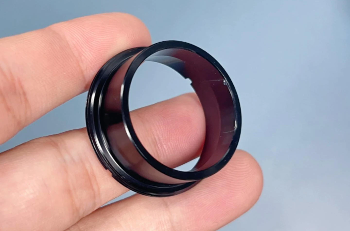
As shown in Figure 1, the buffer sleeve demands exceptionally high dimensional accuracy and geometric tolerances during machining.
Operators must carefully monitor the 0.25° milling tolerance, coaxiality, and perpendicularity.
Furthermore, this buffer sleeve falls within the category of thin-walled part machining, presenting significant challenges in workpiece clamping.

During clamping, poor radial rigidity makes the part prone to deformation, hindering tolerance and technical requirements.
To prevent deformation, axially clamp the machined end on a mandrel, fix the pin in the keyway with a nut, and protect dimensional accuracy and tolerances.
Analysis of Causes
Impact of Clamping Force on Machining Deformation.
In past buffer sleeve machining with three-jaw CNC lathes, weak clamping caused rotation, while excessive force caused deformation.
Clamping force directly impacts positioning stability and secure holding.
Figure 2 illustrates the effects of a three-jaw self-centering chuck during part clamping.

a—Clamping thin-walled workpiece for bore turning
b—Isometric deformation of thin-walled bore
Utilizing slotted sleeves or fan-shaped flexible jaws for part clamping increases the clamping surface area.
Adjust the hydraulic chuck to optimal force, improving the buffer sleeve’s dimensional accuracy and tolerances (Figure 3).

Precision impact from multiple clamping operations.
Re-clamping the workpiece and the tight 0.25° chamfer tolerance prevented meeting machining requirements, causing a batch of parts to be scrapped.
Control and Improvement
Selection of Machining Equipment.
Operators machined the buffer sleeve on the INTEGREX300-IV Yamazaki Mazak turning-milling center to ensure quality and reduce scrap (Figure 4).

This machine features a dual-power chuck and a high-precision infrared probe, ensuring dimensional accuracy in part machining.
> Fixture Design and Machining
After the turning-milling center machines the OD, inner bore, and four R6mm arcs, three 0.25° outer bevels still require milling.
The 0.25° bevel represents the most challenging dimension to guarantee and control for this part. Engineers designed a fixture to ensure clamping accuracy.
Per fixture design specifications, the material must possess sufficient strength, toughness, and excellent wear resistance. Engineers selected ductile iron.
Mounted on a mandrel, the workpiece still needs extra constraints to control Z-axis and rotation for chamfer milling.
A ball-end mill cuts a keyway in the fixture, and a pin in it limits the workpiece’s Z-axis rotation.
A clamping nut secures the workpiece to restrict translational movement in the Z-direction.
Engineers term this type of positioning, where all six degrees of freedom are uniquely constrained, complete positioning.
Based on drawing analysis, a helical clamping mechanism is adopted. Engineers select the insert key method for fixture design, considering rotational freedom (Figure 5).

The machining of the 0.25° bevel on the part’s cylindrical surface utilizes this helical clamping mechanism for secure holding.
> Fixture design and machining process
The fixture design and machining process are as follows:
First setup: Rough and finish internal features; rough external cylinders, leaving finish allowance.
Second setup: Finish external diameter and secure length tolerances on a turning-milling center.
First article inspection: Utilize the in-line measurement system to perform dimensional compensation on the part.
Rough and finish the four R6mm open arcs and 0.25° chamfers on the end faces;
Start batch production; measure dimensions on the first part, then monitor tool wear and replace inserts as needed.
Analysis of Machining Results
The 0.25° chamfer on the part’s cylindrical surface is one of the critical dimensions and also the most challenging to guarantee and control.
If the machining accuracy of this dimension exceeds the tolerance range, it will directly result in scrap production.
During machining, the INTEGREX300-IV’s online measurement detects part position and updates the program to ensure bevel accuracy (Figure 6).

Significance of the In-Process Measurement System.
Manufacturers equip most CNC machine tools with in-process inspection systems.
This creates a closed-loop system integrating machining, inspection, calculation, and correction, significantly enhancing production yield.
In-process measurement not only serves a vital role in workpiece inspection but also offers unique advantages in workpiece clamping and alignment.
Operators substantially improve clamping accuracy by calculating and correcting workpiece coordinates.
Principle of Online Measurement Systems.
For measurement, install a probe, move its tip to the workpiece, and let the CNC system record coordinates in real time.
Operators calculate the measured point’s actual coordinates from the probe-workpiece spatial relationship.
After obtaining the measured point coordinates, operators calculate geometric positions to derive the final results.
Measurement and Machining of the 0.25° Bevel.
Operators measure the clamped part’s outer cylinder online, record errors on the 0.25° bevel, and have the CNC system generate G-code to machine it (Figure 7).

Comparison Before and After Machining Method Modification.
By analyzing issues and improving the method, operators ensured the buffer sleeve’s dimensional and geometric accuracy in subsequent machining.
Conclusion
This study analyzes the excavator buffer sleeve, examining clamping force effects on deformation and designing a fixture to control it.
Operators machined the parts using a Yamazaki Mazak INTEGREX300-IV turning-milling composite machining center.
Operators used the machine’s online real-time measurement system to measure and align the challenging 0.25° inclined surface.
Measurements confirmed effective control of the buffer sleeve’s milling angles, cutting scrap by 30% and meeting production requirements.
Comparative analysis demonstrated not only controlled milling dimensions but also enhanced dimensional stability.

