
The rapid advancement of modern manufacturing has placed increasingly stringent demands on the precision, quality, and production efficiency of mechanical components.
As critical elements within mechanical transmission systems, the machining accuracy and surface quality of sleeve-type components directly impact the overall performance of the machinery.
Traditional turning and milling methods suffer from several issues. These include dispersed processes, low efficiency, and difficulty in ensuring precision.
As a result, they are inadequate for meeting modern manufacturing demands, particularly for high-quality, high-efficiency sleeve part processing.
In contrast, CNC machining technology has gained widespread adoption in mechanical processing due to its advantages of high precision, efficiency, and flexibility.
As a vital branch of CNC machining, turning-milling composite technology integrates both turning and milling functions within a single machine tool, enabling efficient and precise machining of complex components.
Applying this technology to sleeve-type parts effectively addresses the limitations of traditional methods, enhancing both processing efficiency and product quality.
This study aims to design machining solutions based on turning-milling composite CNC processes tailored to the structural characteristics and machining requirements of sleeve-type components.
It involves optimizing process parameters and conducting machining process simulations to provide technical support for the efficient and precise machining of such components.
The anticipated outcomes will offer new approaches and methodologies for efficient, high-precision machining of sleeve-type components.
This will advance the application and development of turning-milling composite CNC technology in mechanical manufacturing.
Overview of Turning-Milling Composite CNC Machining Technology
Basic Concepts
Turning-milling composite CNC machining technology is a highly efficient method integrating turning and milling operations.
By performing multiple machining functions on a single CNC machine tool, it significantly enhances processing efficiency.
Operators utilize the CNC system to precisely control the machine tool.
This enables them to complete turning and milling processes consecutively on the same workpiece without performing multiple setups or adjustments.
The fundamental principle of this technology involves the CNC system controlling the machine tool’s spindle and feed axes to achieve tool movement in different directions.
The turning component primarily processes the outer circumference, internal bores, and end faces of rotationally symmetric parts.
Operators use the milling component to machine complex contours and grooves.
The integration of both functions enables this technology to meet the machining demands of various complex parts.
Compared to traditional turning and milling processes, turning-milling composite CNC machining offers significant advantages.
It reduces the number of workpiece setups, avoiding cumulative errors from multiple setups and thereby enhancing machining accuracy.
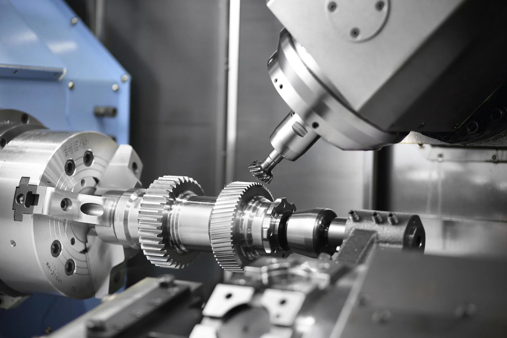
Simultaneously, this technology enables continuous multi-process machining, shortening inter-process waiting times and substantially improving production efficiency (as shown in Figure 1).

Technical Features
Turning-milling composite CNC machining technology holds a significant position in modern manufacturing due to its unique characteristics.
1. High-precision machining capability.
Through precise control by the CNC system, this technology achieves micron-level machining accuracy.
This is particularly crucial for high-precision components like bushings.
It ensures not only dimensional and geometric conformity to design specifications but also significantly enhances component fit accuracy.
2. Exceptionally high machining efficiency.
Traditional turning and milling processes often require multiple setups, whereas turning-milling composite CNC machining completes multiple operations in a single setup.
This reduces inter-process waiting time and setup errors, substantially boosting production efficiency.
For example, when machining sleeve components, this technology simultaneously performs external turning, internal bore machining, and end-face milling, significantly shortening the processing cycle.
3. Multi-functional machining capability.
Traditional turning and milling processes typically limit operators to single-type operations.
In contrast, turning-milling composite CNC machining enables multiple functions—including turning, milling, drilling, and tapping—on a single machine.
This versatility allows it to handle diverse complex part requirements, further expanding machining scope and improving equipment utilization.
CNC Turning and Milling Composite Machining Process for Sleeve Components
Technical Analysis of Sleeve Components
The sleeve components used in this study employ 45 steel as the material, with bar stock as the raw material measuring 110mm x 120mm.
The positioning reference for the parts utilizes the centerlines with tolerances of 35H7 and 100f9, along with the bottom end face of the sleeve.
Additionally, operators must meet stricter requirements for precisely positioning the 100f9 outer diameter when machining the 35H7 surface.
It must be within 0.05mm tolerance on the outer circumference, with complete part dimensions marked. Tolerances must meet industry standards.
Machine Tool and Fixture Selection
During the machining of sleeve components, conventional CNC machines typically require multiple setups to complete all processes.
This not only extends the overall processing time but also increases the likelihood of machining errors.
The project team selected the HTC2050Z turning and milling center to address this issue.
Equipped with a FANUC Oi-TC CNC system and a 12-tool magazine capacity, this machine meets diverse machining requirements.
Regarding fixture selection, the HTC2050Z comes standard with a three-jaw chuck that provides stable clamping force, ensuring positioning accuracy during machining.
To guarantee machining precision, operators selected the left-end outer diameter and end face of the sleeve part as the roughing and finishing reference surfaces.
These surfaces were machined into roughing references via turning processes.
Subsequently, the three-jaw chuck was used for clamping and positioning to ensure accuracy for subsequent machining operations.
In CNC machining, the selection of the programming origin directly impacts machining accuracy.
This document designates the programming origin at the right end face of the sleeve part, with the positive directions of the X and Z axes.
This facilitates programming operations for operators and effectively reduces machining errors.
It enhances machining efficiency and improves the accuracy of each process step, thereby ensuring the quality of the final product (as shown in Figure 2).

Key Principles for Formulating Composite Reinforcement Process Plans
1. Benchmark Priority Principle.
During machining, operators first select and machine the reference surface to serve as the positioning benchmark for subsequent operations.
For sleeve components, the selection and machining accuracy of the reference surface directly impact the precision of follow-up processes.
When formulating machining plans, operators should prioritize machining the reference surface to ensure its accuracy meets subsequent processing requirements.
2. Rough-Finish Sequence Principle.
This principle requires initial rough machining to remove the majority of stock, followed by finish machining to achieve final dimensional accuracy and surface quality requirements.
For sleeve components, rough machining primarily aims to rapidly remove material and reduce processing time, while finish machining ensures the final dimensional accuracy and surface quality.
Therefore, when formulating machining process plans, personnel must rationally arrange the sequence of rough and finish machining to comprehensively enhance processing efficiency and quality.
3. Process Concentration Principle.
This principle involves grouping multiple machining processes together to reduce clamping operations and improve processing efficiency.
Particularly in sleeve component machining, operators perform multiple operations, including turning, milling, and drilling.
Operators must fully implement this principle to effectively reduce clamping frequency and boost efficiency.
When formulating machining plans, arrange operations rationally based on the part’s structural characteristics and processing requirements, aiming to complete multiple tasks within a single setup.
Process Route Design
CNC machining technology offers advantages such as high precision, high efficiency, and high automation, significantly enhancing part quality and production efficiency.
In the machining of sleeve components, designing the process route for integrated turning and milling CNC operations is particularly critical.
Through rational process route design, machining time can be effectively reduced, machining accuracy improved, and production costs lowered.
In sleeve component machining, operators perform multiple operations, including turning, milling, and drilling.
Operators must fully implement this principle to reduce clamping frequency. This approach also helps boost machining efficiency.
Milling Plane Toolpath Design
In the turning-milling composite machining of sleeve components, designing the milling plane toolpath is crucial for enhancing processing efficiency.
To achieve high-efficiency cutting, this paper proposes employing rectangular ring-cutting in the XY direction while implementing layered cutting in the Z direction with a layer height of 2mm.
Rectangular ring cutting is an efficient toolpath strategy. By forming multiple annular cutting paths in the XY plane, it effectively reduces idle travel time and boosts cutting efficiency.
In practice, the tool rapidly moves from the initial position to the workpiece edge to commence the first layer of cutting.
The tool then performs annular cutting along the workpiece edge, with the cutting path gradually contracting inward to form multiple annular paths.
The width of each ring path is adjusted based on the workpiece dimensions and tool diameter.
Between each ring path, the tool switches paths via rapid movement (G00), minimizing idle travel time.
When the tool reaches the workpiece’s center, operators complete the first layer of cutting.
This rectangular ring cutting method creates multiple ring paths in the XY plane, effectively reducing idle travel time and improving cutting efficiency.
In the Z-direction, a layered cutting approach is employed with a 2mm cutting depth per layer.
Cutting begins at the workpiece surface with an initial 2mm depth.
After completing the first layer’s rectangular ring cutting in the XY plane, the tool rapid-moves to the next layer’s starting position and continues rectangular ring cutting, maintaining a 2mm depth per layer.
Subsequently, the tool cuts layer by layer downward until reaching the predetermined cutting depth.
This layered cutting method effectively controls the cutting depth, ensuring machining quality while improving cutting efficiency.
Cutting Path for Bore Turning
Bore turning presents greater challenges than external turning due to its confined space, which restricts tool feed and retraction paths, increasing the risk of collisions between the tool, workpiece, or fixture.
Additionally, the direction of cutting forces in bore turning is opposite to that in external turning, making tool vibration and workpiece deformation more likely, thereby affecting machining accuracy.
♦ Setting a Proper Starting Point
To prevent tool collisions during internal turning, the starting point should be positioned outside the right end face.
This ensures sufficient space for tool adjustment and positioning before entering the bore, avoiding contact with the workpiece.
Initiating the cut from the outer right end face enables an outward-to-inward machining path, facilitating control over cutting forces and speeds while minimizing tool vibration and workpiece deformation.
Starting the cut from the outer right end face allows chips to discharge naturally, preventing chip accumulation inside the hole that could shorten tool life.
♦ Feed Path and Layered Cutting Strategy
When designing the feed path for internal boring, layered cutting is employed to reduce cutting forces and tool vibration.
Material is removed layer by layer, with the cutting depth per layer selected based on tool strength and workpiece material properties.
The feed path for internal boring employs a helical feed approach, progressively advancing from the outer to inner surfaces.
This effectively controls cutting forces and speeds, minimizing tool vibration and workpiece deformation.
♦ Using G90 Internal Cylindrical Fixed Cycles
To enhance machining efficiency and accuracy, G90 internal cylindrical fixed cycles are utilized for internal boring.
This enables repeatable fixed-cycle machining, reducing programming workload and improving productivity.
During G90 internal cylindrical fixed-cycle machining, operators first position the tool beyond the right end face of the sleeve part.They then set the starting point.
After that, they configure the G90 cycle parameters—such as cutting depth, feed rate, and cutting speed—according to the workpiece dimensions and machining requirements.
Next, the G90 command is initiated, and the tool performs internal bore turning according to the preset cycle parameters.
After each cycle completes, the tool automatically returns to the starting point, ready for the next cycle.
Following each cycle, the machining quality is inspected to ensure the internal bore dimensions and surface finish meet specifications.
Drilling Feed Path
During the fixed cycle for hole machining, the tool rapidly positions to the initial location and R point to perform drilling operations.
At the hole bottom, it executes tool movements, pauses, and automatically returns to the R point plane.
For the end-face hole 35H7 on the sleeve part with a depth of 80mm and the 2-M6 pilot hole depth of 25mm, the fixed cycle employs staged drilling.
Recirculating chip removal is utilized for depth control, strictly adhering to G83 requirements for drilling operations.
♦ Axis Switching and Safety Precautions for Radial Hole Machining
When the center point of radial hole 2x15H7 deviates from the workpiece rotation axis, operators must promptly switch the power tool to the axis and radial power tool.
Simultaneously, before operating the machine, activate the hydraulic switch to adjust the milling power axis, X-axis, Y-axis, and rotation axis.
Bring all axes back to their initial positions. During this process, ensure they do not come into contact with the tailstock.
When the rotary axis returns to its initial point, input C0 into the system and switch to MDI mode.
Use the M70 and M71 commands in accordance with the sleeve part machining requirements. Apply the M70 command for turning operations.
Use the M71 command for end-face drilling. These commands ensure successful conversion to rotary axis mode (as shown in Table 1).
After completing all internal hole drilling, external turning, and end-face drilling operations, switch to the milling power spindle to perform radial hole drilling and surface milling operations.

♦ Importance of Process Route Design for Sleeve Components
The design of the turning-milling composite CNC machining process route for sleeve components is a critical factor in ensuring both machining quality and production efficiency.
In the design of the feed path for internal bore turning, the selection of the starting point and the optimization of the feed path are particularly crucial.
By rationally selecting the starting point and adopting layered cutting, safety incidents such as tool collisions can be effectively avoided.
Using helical feed methods further reduces the risk of collisions. Together, these measures enhance both machining quality and efficiency.
Furthermore, employing the G90 cylindrical fixed cycle for internal bore machining can further enhance processing efficiency and precision.
It also reduces the programming workload. At the same time, it strengthens overall process safety.
Concurrently, during actual production, the machining process route should be flexibly adjusted based on specific workpiece materials, dimensions, and processing requirements.
Continuous optimization of the process route will further elevate the machining quality of sleeve components. It will also improve production efficiency.
These improvements help meet the demands of modern manufacturing for high-precision and high-efficiency processing.
Conclusion
In summary, this paper demonstrates the significant advantages of integrated turning and milling CNC machining technology in processing sleeve components through in-depth research.
By leveraging precise CNC system control and optimized machining process route design, this technology enhances machining accuracy and efficiency.
It also substantially reduces clamping operations. In addition, it helps minimize cumulative errors.
As the manufacturing industry increasingly demands high-precision, high-efficiency machining, integrated turning-milling CNC technology will play an even more vital role in the future.
Future research can further explore its application in machining more complex components and investigate how technological innovations can further enhance its machining capabilities and efficiency.

