
During production, manufacturers usually classify irregularly shaped parts as special-shaped parts, which have unique structural features according to their specific uses.
Due to their different functions and application environments, their technical requirements are also different. Therefore, there are no fixed rules for all shapes of parts.
Special-shaped parts do not have regular shapes and are mainly used to solve the positioning and clamping problems of workpieces in production.
The mass production of parts ensures the accuracy of parts processing, meets the needs of clamping premise, shortens processing time and improves production efficiency.
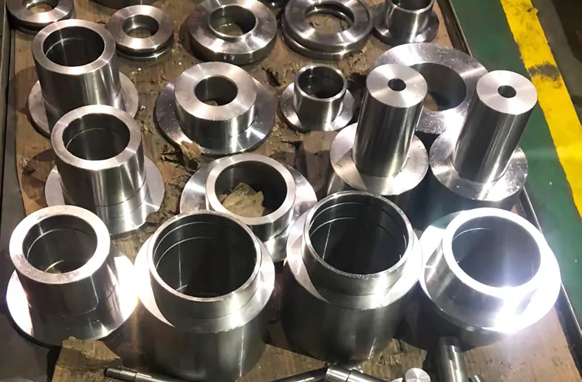
As shown in Figure 1, the part has a complex shape and structure and requires multi-faceted processing with high precision.

For such cases, it is impossible to complete the processing by using a vise directly on a three-axis machining center.
To address this issue, engineers designed a series of fixtures to support the machining process.
These clamps can be clamped quickly and easily, ensuring machining accuracy and improving production efficiency.
Part characteristics and technical requirements
Part properties.
The maximum profile size of 3.9311 (inch) × 3.3711 (inch) × 1.445 (inch) is a tapered part consisting of two precision holes ø 0.5910 (+ 0 / – 0.0005) and ø 0.9450 (+ 0 / – 0.0005), whose axes intersect at 6.0000 (+ 0.005 / – 0).
There are grooves in the middle of both sides of the part, one end of ø0.9450 has a clamping groove and a limit, and the other end has threads and a curved surface.
The part has a complex shape and structure and requires high machining accuracy, especially at the intersection of the two precision hole axes.
The size of this intersection is a critical functional dimension and is difficult to control.
Technical Analysis
The part’s dimensions and surface roughness must be no less than Ra63. The overall processing strategy is: rough milling of the blank -> milling -> end shape -> fine milling of two precision holes -> milling of the middle slot.
Rough milling of blank (process number: OP10)
Saw the workpiece to 4.0 inches by 4.0 inches by 1.575 inches. Clamp the blank through the thickness. Mill one side using a ø60 mm face mill at a 7.5° angle to the workpiece centerline. Ensure the small end dimension is no less than 2.810 inches.
Then, rotate the workpiece and clamp it again in the thickness direction with the machined surface facing downward, and use a 7.5° bevel block to level the bottom of the workpiece.
Next, use a ø60 mm disc milling cutter to mill the other side at a 15° taper angle relative to the upper machining surface. Finally, use the same ø60 mm disc milling cutter to mill the remaining side.
The other side of the 60mm disc milling cutter tapers 15° with the side of the upper step, and the small end size is 2.8in, as shown in Figure 2.


Precision milling profile (Process No. OP20)
Special fixture, using the previous process 15 ° taper to eliminate clearance, the bottom surface screw pressure, with four-axis positioning machining method, first 0 ° processing small arc end of the outer row, and then – 15 ° processing of the large arc end profile, and finally – 7.5 ° clearance.
The two sides of the arc center axis intersect at a size of 5.76, as shown in Figure 3; fixture design points and the production process are shown in Figure 4.
Fig. 4 Schematic diagram of 4-axis machining fixture.
Design points:
According to the principle of datum coincidence, the center of rotation and the intersection point of two axes coincide, minimizing the error.
Production process:
Material 45 #, the first two small pieces welded into a whole, and then use the machining center on both sides of the four-axis rotary center tab, milling, milling waist-shaped groove, and finally use the four-axis fixed-angle machining 3 2 and 3 3 process with the shape.
Four-axis precision milling of both sides of the precision hole (Process No. OP30)
( 1) The shape from the previous finishing process matches the fixture taper with the clearance elimination. Apply screw pressure at the bottom of the small hole end.
Fix the angle using the four-axis positioning at -90° and -105° to machine the two small tapered planes at the small end. Then, rotate to the 75° position to perform drilling and reaming.
Machine the ø0.5910 (0 / -0.005) precision holes at this stage.
( 2) Pause the program. Loosen the screws on the big-end hole side. This allows the small-end hole side screws to apply compression.
Use four-axis positioning to rotate to the 105° position for rough milling the profile. Finally, drill and tap the ø0.9450 (0 /—0.005) fine hole by boring in place. At the same time, machine the spring groove in this step. This ensures the required positional accuracy between features.
During the machining process, check that the intersection of the axes of the two fine holes is ø0. 5910 (0/- 0.005) and ø0. 9450 (0/- 0.005) is at the dimension of 6.125 (+ 0.005/0), as shown in Fig. 7.
Fixture design points:
In addition to the principle of datum coincidence, this design allows the operator to self-check whether the size is qualified without disassembling and assembling the fixture.
Small hole end milling slot (work order number: OP40)
Special fixture (as shown in Fig. 5), 0 5910 fine hole positioning, movable jaws side clamping, with a torque wrench to control the clamping force of 2kg, to avoid deformation of ø0. 5910 (0/- 0.005) fine holes processed in the previous process due to excessive clamping force.
Roughing and finishing milling intermediate slot: Processing this part requires special attention to the choice of cutting dosage.
The tool diameter can not be too large, reducing the friction area between the tool and the workpiece. Reduce resistance and internal stress to avoid deformation of the workpiece.
For roughing, choose a 20-mm diameter milling cutter, 𝑎p = 0.030in, 𝑓z = 0.005in, and for finishing, choose a 12-mm diameter milling cutter, 𝑎p = 0.2in (side cutting edge), 𝑓z = 0.001in.

3.5 Large Hole End Milling (Process No. OP50)
The core is machined in four axes with a hardened three-jaw chucked mandrel. The other end is tightened with a tailstock.
The shaft is fitted with a ø 0.5910 precision hole, and a pin is used to stop the rotor. The notch is machined at 125° and 20° angles, as shown in Fig. 6.

Analysis and solution of machining difficulties
Ensure the functional size at this intersection of the two size axes is challenging, but this is not the most difficult part of the processing.
The key is how to check whether the parts are qualified. The size of the use of the three coordinates is challenging to control effectively because it is a virtual intersection.
It is very easy to produce small results that push the phenomenon of significant, misleading test results further.
A special inspection jig (Figure 7) was designed to inspect the author’s problem according to the designer’s intention and use of functionality.
The three readings proved that the table jumps in the range of 0.010 are qualified.
Principle of the inspection jig.
This part needs another part to become a mechanism to play its role.
After combining the two parts to match, the axes intersect at one point. The designer used this intersection point as the checker’s rotation point.
This is because the rotation point does not maintain the ideal position during movement.
As the rotation point moves toward the sphere’s center, the percentage gauge contacts the sphere’s surface with consistent readings at any point.
The clever use of this principle, with a three percent gauge to test it, involves running in different directions.
This helps to detect the component of each direction of the runout.
As a result, it can accurately simulate several parts. This is useful in analyzing the cumulative error in their combination.

Precautions for machining parameters
Tool selection
As the workpiece is an aluminum alloy, processing should maintain the tool’s sharpness.
A preferred two-flute milling cutter facilitates chip removal. A boring tool boring processing mode should be selected for precision holes.
Regarding tool rigidity, high-speed steel is more appropriate because the high-speed steel tool edge is generally sharper than the carbide tool.
To reduce stress deformation in the cutting process, boring should choose the tip of the smaller R, with a chip removal groove, and a smooth cutter particle.
Cutting parameters
Since the milling cutters used in the processing are all solid carbide milling cutters, the cutting parameters are as follows.
Cutting speed Vc=300~600 (m/min).
The axial cutting depth of rough milling 𝑎p = 0.75 ~ 1.50 (mm).
Finishing cutting depth 𝑎p = 0.10 mm.
The draft angle of each tooth in rough machining is 𝑓z = 0.10mm; the draft angle of each tooth in fine machining is 𝑓z = 0.10mm.
The draft angle of each tooth in rough machining is 𝑓z = 0.10mm; the draft angle of each tooth in fine machining is 𝑓z = 0.05mm.
Since aluminum parts have good cutting performance but are easy to deform, the cutting parameters should follow the following principles: large linear speed Vc, small axial draft 𝑎p, and large feed rate F.
Precautions during processing
(1) Aluminum has low strength. In the later stage of the clamping process, when most of the material is removed, care should be taken to avoid excessive clamping force and deformation.
If necessary, a torque wrench can be used to keep the clamping force consistent.
(2) The workpiece size requirements are very high, and the machining accuracy of the machine tool depends largely on the accuracy of the machine tool.
Each time the machine tool is adjusted, the repeatability and clearance of the four axes should be checked so that appropriate compensation can be made.
(3) Check the accuracy of the fixture and the accuracy of its fit with the four axes.
in conclusion
After repeated cutting verification, the above process for processing the part is convenient and reliable in clamping, and the processing accuracy is easy to ensure and stable.
The inspection accuracy of the special inspection fixture is very reliable, and the customer has unanimously approved the processing and inspection of the part.

