
As the level of intelligence in manufacturing continues to advance, CNC machine tools—as core equipment in modern manufacturing—face increasingly stringent demands for automation and machining precision.
The tool holder system, a critical component of CNC machine tools, directly impacts both machining efficiency and product quality.
In-depth research into the operational mechanisms of tool holders holds significant importance for enhancing equipment maintenance standards.
Tool Holder Structure and External Electrical Control
The lathe tool holder is the mechanism for automatic tool changing on a lathe, serving as a critical component.
It mounts various cutting tools, and its structure directly impacts the machine tool’s cutting performance and operational efficiency.
Tool holders come in many types: simple holders using Hall effect sensors for tool position detection, automatic holders with position encoders enabling bidirectional tool changing, and motorized holders capable of driving tools.
Rotation control employs either standard AC motors or servo motors, with varying tool turret models.
Typically, tool change control requires functions such as identifying the current tool position and comparing it with the target position.
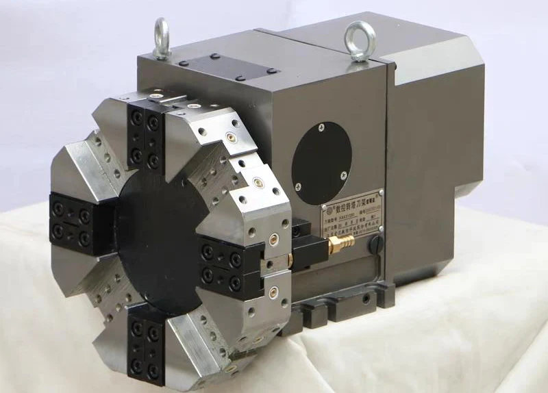
Common tool turrets in CNC machines fall into two main categories: vertical turrets and horizontal turrets, as shown in Figure 1 and Figure 2.


The turret tool holder is a widely adopted tool holder configuration that achieves automatic tool changing on machine tools through turret rotation, indexing, and positioning.
Comprising the tool holder body, tool turret (4-station), positioning mechanism (end gear/Hall effect sensor), motor (standard or servo), and worm gear transmission, it completes tool changes through PMC control of motor rotation, worm gear reduction, turret indexing, and locating pin locking.
Electrical Control
The simplified four-sided tool holder employs a three-phase AC motor control system.
By regulating the motor’s forward and reverse rotation in conjunction with the mechanical structure, it achieves forward rotation, reverse rotation, positioning, and locking functions.
Operators control motor direction and stopping by switching the circuit logic, which actively changes the phase sequence of the stator winding power supply.
This change reverses the rotating magnetic field, enabling the motor to rotate forward or backward.
Operators stop the motor by disconnecting the power or interrupting the circuit.
The most classic approach is the interlocking circuit using contactors and pushbuttons, which prevents simultaneous energization of forward and reverse contactors that could cause a power short circuit.
The circuit primarily consists of a main circuit and a control circuit.
The main circuit directly connects to the three-phase power supply (L1, L2, L3) and the motor (M).
Its core components are two AC contactors, KM1 and KM2, whose main contacts control the phase sequence of the motor’s power supply.
The control circuit comprises equivalent pushbutton relays (Y2.2 for forward rotation, Y2.3 for reverse rotation) and relay coils (KA1, KA2), with the core being the interlocking logic.
This logic interlock is added within the PMC program.
The electrical control hardware circuit, including the main circuit and control loop for the four-way tool holder, is shown in Figure 3.

Quad Tool Changer Workflow
The quad tool changer workflow operates by entering tool selection commands T1-T4 on the CNC machine control panel.
The CNC then transmits the tool number (T code) to the PMC for reception and processing.
Upon receiving the tool selection signal, the PMC controls the motor’s forward/reverse rotation to drive the tool turret.
The turret selects the nearest tool. During rotation, the tool turret receives position data from Hall sensors or encoders for precise positioning.
Reversing the motor mechanically locks the end tooth disc, and finally, a tool selection completion signal is fed back to the CNC.
During manual tool changes, pressing the tool change button allows sequential tool selection in the same rotation direction.
When the tool turret changes tools, the PMC program typically handles processes such as identifying the tool number at the current working position and determining whether the tool number falls within the change range.
PMC controls the rotation of the tool turret motor to manage tool selection.
Manual and Automatic Tool Changer (PMC) Programs
Manual and automatic program address allocation, as shown in Table 1.

Automatic Tool Change Execution Conditions
Figure 4 shows the tool selection signal connection. When the CNC machine receives the T command, it activates R119.0.
The CNC machine transmits the F signal to the PMC.
F7.3 is the acknowledgment signal sent by the CNC system to the PMC after receiving the T command, while F1.3 is the feed axis inhibit acknowledgment signal.

Figure 5 shows the T-tool number coding program, and Table 2 presents the tool number coding table.


Figure 6 transfers the lower four bits of memory location R120 to the K register.
This transfer facilitates tool code determination.
When the required tool number is entered via the CNC machine panel, the CNC system generates the corresponding binary code in F26.
The COIN instruction compares the K memory unit with the tool code signal.
When the data in K9 matches the data in F26, the system generates an output signal, closes the intermediate relay, and completes tool identification.
Similarly, the system can handle error messages when operators input illegal commands or enter TO.
Detailed explanations of function instructions can be found in relevant FANUC documentation.

Manual and Automatic Tool Selection Implementation Method
(a) Jog to the Next Tool Position.
- Step 1: X0.2 drives the Y2.3 tool holder motor to rotate forward.
- Step 2: Locate the next tool position within the specified time.
- Step 3: After Y2.3=0 undergoes a specified buffer time, drive the motor to reverse.
- Step 4: After Y2.2 reverses and retracts for the specified time, Y2.2 disconnects.
Program the tool holder motor rotation, set the connection conditions and stop signals to enable forward/reverse and stop functions.
The forward/reverse/stop circuit represents a typical control circuit, so we will not elaborate on it here.
(b) Manual Tool Selection.
Operators must perform manual tool selection in manual mode. During programming, they should set the machine to manual selection mode.
The difference lies in Step 2: do not set a reverse time until X0.2 disconnects. All other steps remain the same.
(c) Automatic Tool Selection.
The difference lies in Step 1: R119.0=1 initiates startup.
Finally, add an auxiliary function to complete signal G4.3, setting G4.3=1, as shown in Figure 7.

The tool change program features rigorous logic, addressing both functional implementation and potential exceptions.
These include scenarios such as tool selection timeout failures due to sensor damage, input of invalid codes, mode selection errors, and motor stalls.
All such cases require thorough handling within the PMC program.
The CNC machine tool’s PMC serves as the “bridge” connecting the numerical control (NC) system with the machine tool’s actuators.
It manages the exchange of logical control signals and employs management, forming the core component enabling automated machining in CNC machine tools.
For the complete program, refer to the machine tool’s built-in program. This document explains only the application principles.
Conclusion
With a solid understanding of the operational principles of CNC machine tool PMC systems, leveraging the diagnostic capabilities of the FANUC system can significantly reduce the time required for maintenance personnel to resolve faults.
By querying I/O input and output states, operators can rapidly pinpoint and resolve faults, thereby enhancing equipment maintenance and management efficiency.
Additionally, engineers can conduct functional development as needed, focusing on PMC-based upgrades such as high-voltage logic modifications for machine tools, safety protection controls, machine tool status management, and customized auxiliary functions.

