Table of Contents
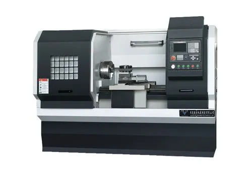
Thread rolling uses a tool to apply pressure, causing plastic deformation that fills troughs, reduces roughness, and cold hardens the surface. This refines the grains, creates a dense fiber structure, and induces residual stress, improving hardness, strength, and overall properties. It is common to use ordinary lathes to roll threads. This article provides a new process solution for thread rolling based on CNC lathes.
CNC horizontal lathe processing of long shaft threads (e.g., hydraulic press tie rods) often results in issues with the threaded bottom, such as right angles or high roughness, which lead to stress concentration and potential fractures. Rolling the bottom of the thread deforms the surface metal plastically.
Rolling the threaded bottom rounds and smooths it, reducing stress and improving thread strength, hardness, and part strength. Currently, most operators use ordinary lathes for manual rolling of the threaded bottom. This method is simpler and easy to adjust during the processing process. Manual operation is prone to damage from misoperation, relies heavily on experience, and struggles with consistent production quality.
CNC lathes automate processing with preset programs, reducing manual work and ensuring consistent quality, but operators cannot stop the machine midway. Additionally, rolling processing differs from cutting processing, so thread rolling requires higher precision and more stringent conditions. Incorrect rolling can damage parts, tools, and even the CNC lathe, posing a greater risk.
Therefore, the industry rarely uses CNC lathes for thread rolling. Technical personnel seek a CNC lathe-based thread rolling method for automatic processing and reduced risks.
Implementation plan
Here’s a brief introduction to the thread rolling plan implementation using the attached figure.
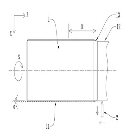
Figure 1 Structural diagram of thread rolling method
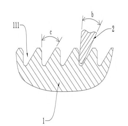
Fig 2 shows the schematic diagram of the cross-sectional structure when the hob inserts into the screw groove.
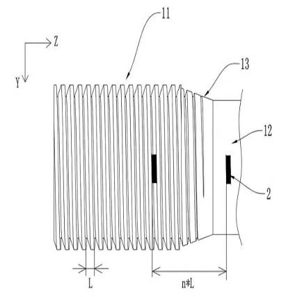
Figure 3 Structural diagram of the thread rolling method from another angle
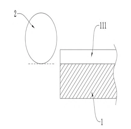
Fig 4 Schematic of the screw groove cross section near the end face.
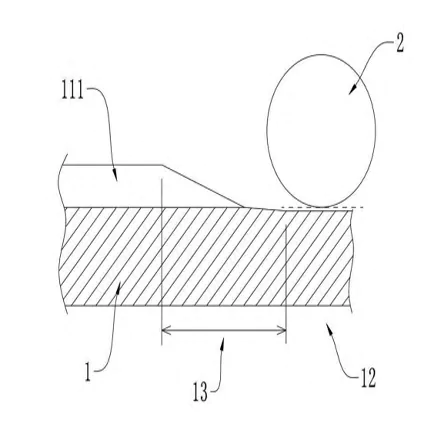
Figure 5 Schematic of the screw groovcross-sectionon when processing the side near the back-cut groove.
In the figure: 1-workpiece, 11-thread segment, 111-screw groove, 12-back-cut groove, 13-transition slope, 2-hob
Specific implementation method
1. Tool Alignment and Z-Axis Positioning
Align hob 2 with thread segment 11 of workpiece 1 to ensure precise movement within screw groove 111. Begin by positioning hob 2 at one side of thread segment 11, using this as the starting point for the Z-axis. Move hob 2 along the Z-axis in integer multiples of the pitch, without further Z-axis movement during alignment. Rotate workpiece 1 and move hob 2 along the X-axis to align screw groove 111 with the hob, ensuring contact at the tooth bottom. Set the X-axis starting point and spindle angle as the machining start angle, adjusting from the original starting angle.
2 . Manual Rotation and Alignment Process
The tool setting method involves moving hob 2 to a multiple of the pitch and stopping along the Z-axis. The operator manually rotates workpiece 1 to align screw groove 111 with hob 2. This method minimizes s Z-axis movement of the screw groove, leading to more accurate adjustments and reduced thread damage.
Hob 2 automatically aligns with screw groove 111 at pitch multiples, reducing the need for precise alignment at the thread end. This simplifies tool setup on the CNC machine, improving accuracy and lowering the risk of processing errors.
3. Transition from Back Cut Groove to Thread Segment
In some embodiments, the tool starts at the back cut groove 12, which has a smaller diameter than the thread portion. The transition bevel 13 connects thread segment 11 and back cut groove 12. The thread end is positioned at the transition bevel 13, creating a bevel transition between the thread root and bevel. The inclined top of the thread reduces the depth from the bevel to the root, narrowing screw groove 111 toward back cut groove 12 (see Figures 3 and 5).
As hob 2 approaches thread segment 11 from the undercut groove 12, it passes through transition slope 13 and engages the screw groove bottom 111. This increases contact pressure and enlarges the screw groove’s cross-sectional size. When hob 2 enters screw groove 111, the thread heights on both sides are low, allowing easier entry (see Figure 5 for a cross-sectional schematic).
4 . Collision Risk and Alignment Considerations
When rolling starts from the cutting side of thread segment 11, using the end face as reference (Figure 4), the tooth bottom may be too high, risking collision with hob 2 under high pressure. Additionally, thread segment 11 may lack chamfer, leading to a high thread height on both sides of screw groove 111.
Hob 2 must precisely align with the thread teeth on both sides to avoid collisions and damage. This solution minimizes the risk of hob 2 hitting the thread bottom or teeth, ensuring smoother processing and reducing thread rolling risks on CNC lathes.
5. Tilting of Hob and Reduced Pressure
In some embodiments, hob 2 moves along the Z-axis while tilting away from thread segment 11 along the X-axis. High pressure and heat during hobbing can cause bearing failure or shaft overload, leading to processing issues or equipment failure.
Tilting hob 2 along the X-axis while moving in the Z direction forms an angle α with thread segment 11 (Figure 1). This reduces the rolling depth, affecting only the section near the retreat groove 12, not the entire thread segment 11. The actual rolling length M (Figure 1) shortens the processing time, reducing rolling pressure.
The rolling pressure decreases during machining. As thread segment 11 of workpiece 1 engages with the nut, the main force acts near the back cutter groove 12, reducing pressure and bearing time on the hob 2 and spindle, minimizing the risk of thread rolling on the CNC lathe.
6 . Multi-Pass Rolling for Load Reduction
In some embodiments, the CNC lathe rolls hob 2 in multiple passes to reduce pressure and load. For the first to fourth cuts, the depth increases by 0.1mm with each pass. From the fifth cut onward, the hob depth remains the same as the fourth pass, trimming the thread root at that depth.
7. Rolling Wheel and Swing Gap Mechanism
In some embodiments, hob 2 includes a rolling seat and a wheel attached to it, with a swing gap that allows the wheel to adjust to screw groove 111. This mechanism reduces thread damage caused by processing errors.
The swing gap between the rolling wheel and seat requires high matching accuracy for hob 2 to enter screw groove 111 from the backing groove 12, reducing position accuracy requirements.
Conclusion
CNC lathes are gaining popularity, gradually replacing traditional Chinese lathes. This article introduces a CNC lathe-based thread rolling method to improve production consistency and reduce misoperation and quality issues when ordinary lathes are unavailable le. It aims to provide a more efficient and reliable thread-rolling solution, advancing mechanical processing technology.

