
Rolls are the core components of metallurgical equipment. Their performance directly impacts product quality and production efficiency.
In recent years, high-speed steel rolls have garnered significant attention for meeting the demands of high-speed, high-load, and long-life rolling applications.
However, machining high-speed steel rolls presents numerous challenges.
For instance, traditional cutting tool materials often suffer from accelerated wear, frequent chipping, and poor machining stability during processing.
Consequently, identifying high-performance tool materials suitable for high-speed steel roll machining has become a key focus in machining technology research.
Polycrystalline Cubic Boron Nitride (PCBN) tools, increasingly applied in high-hardness material cutting, have emerged as a crucial solution to overcome these processing bottlenecks.
This article systematically analyzes the machining difficulties of high-speed steel rolls by examining their processing characteristics.
It then introduces PCBN tool application solutions to serve as a reference for machining cast high-speed steel rolls.
Challenges in Machining Cast High-Speed Steel Rolls
Machining cast high-speed steel rolls primarily faces the following challenges.
First, the surface layer of high-speed steel rolls exhibits high hardness, reaching 85–93 HSD after heat treatment.
During rough machining, cutting tools must withstand intense cutting forces and high-temperature loads.
Conventional tool materials are highly susceptible to rapid rake face wear and chipping under these conditions, making it difficult to maintain stable machining.
Particularly during interrupted rough turning, tools endure frequent high-frequency impacts, demanding exceptional toughness and thermal stability.
Second, the carbides dispersed throughout the roll material exhibit significant non-uniformity.
When the tool’s cutting path traverses these hard points, a “strike” effect occurs at the cutting edge, leading to microcrack propagation and chipping.
Furthermore, these carbides often reside at grain boundaries, increasing the cutting resistance of the matrix structure.
This exacerbates cutting deformation, elevates energy consumption, and heightens machining difficulty.
Third, the surface layer of the roll exhibits minute irregular pits and residual stresses resulting from solidification shrinkage or heat treatment, manifesting as pronounced discontinuity during cutting.
This makes any clamping looseness or tool defects prone to rapid failure.
Consequently, cutting tools for cast high-speed steel rolls must use materials with exceptional wear resistance and impact toughness.
They should also be complemented by optimized cutting parameters and tool geometry design.
Advantages of PCBN Tools in Machining Cast High-Speed Steel Rolls
Ultra-high Hardness and Thermal Stability Enable Stable Cutting Under Heavy Loads
PCBN’s hardness ranks second only to diamond, typically reaching 7000–9000 HV on the Vickers scale—far exceeding cemented carbide (1600–1800 HV) and ceramic tools (2000–2500 HV).
Furthermore, its stable crystal structure provides exceptional thermal stability, retaining over 80% of its room-temperature hardness at temperatures exceeding 1000°C.
When machining cast high-speed steel rolls, cutting zone temperatures reach 800–1100°C.
Conventional tools soften significantly under these conditions, whereas PCBN tools maintain edge strength, effectively resisting rake face wear and delaying edge degradation.
This characteristic allows PCBN to achieve extended continuous cutting during heavy-duty rough machining of high-hardness materials.
It also significantly reduces the risk of premature failure caused by thermal wear.
High Wear Resistance and Chipping Resistance, Capable of Withstanding High Carbide Structure Interference
Cast high-speed steel roll materials contain approximately 20% high-hardness carbides, including VC, Mo2C, and W2C.
These carbides measure about 220 μm in particle size, exhibit very high hardness, and are unevenly distributed. Their uneven distribution often causes point-impact damage to the edges of cutting tools.
PCBN tools typically exhibit compressive strengths ranging from 4.5 to 6.5 GPa, delivering exceptional resistance to mechanical fatigue.
Additionally, benefiting from the strong bonding between CBN grains and its inert crystal structure, PCBN tools effectively resist scratching and impact from carbides.
In contrast, ceramic tools are hard but brittle, while cemented carbide tools are tough but wear quickly. PCBN tools offer performance characteristics that fall between ceramic and cemented carbide tools.
This makes them particularly suitable for complex microstructures involving repeated “soft-hard-soft” cutting cycles.
PCBN Tools Demonstrate Excellent Adaptability to Interrupted Cutting, Enabling Highly Reliable Machining of Complex Surfaces.
Residual stress fields and casting shrinkage cavities exist in the surface layer of cast high-speed steel rolls.
During turning operations, these features frequently cause interrupted cutting. This interrupted cutting is accompanied by high-frequency thermal and mechanical shocks.
PCBN tools mitigate the brittleness inherent in traditional ceramic tools by incorporating a toughened matrix. Its fracture toughness significantly exceeds that of alumina ceramics.
During interrupted cutting, PCBN edges experience more uniform stress distribution, resisting structural fragmentation.
Even under cyclic impact from cutting-in and cutting-out motions, they maintain stable cutting performance. Furthermore, PCBN tools can accommodate edge treatments such as blunting, chamfering, and micro-rounding.
These treatments provide superior durability and dimensional stability under high-impact conditions.
Key Considerations for Applying PCBN Tools in Machining Cast High-Speed Steel Rolls
Although PCBN tools offer outstanding performance advantages, their effectiveness depends on a compatible machining system. It also requires appropriate process parameters and standardized usage methods.
When machining cast high-speed steel rolls, due to the material properties and complex operating conditions, seven key aspects must be addressed to ensure optimal PCBN tool utilization.
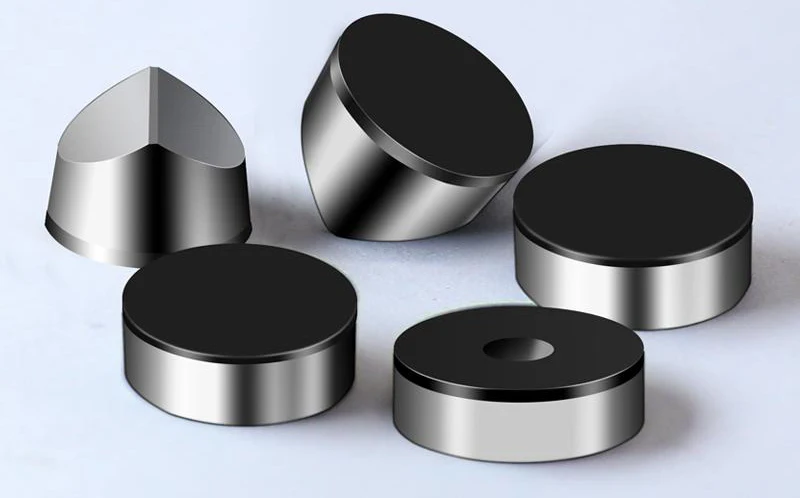
Selecting the Right Tooling
When machining cast high-speed steel rolls, metal-bonded PCBN tools should be selected based on workpiece hardness, cutting method, and operating conditions.
The cubic boron nitride (CBN) content should be controlled between 50% and 70%. This ensures a balance between material toughness and impact resistance.
It also meets the requirements for rough machining and interrupted cutting conditions. Avoid ceramic-bonded or highly brittle super-hard tools, especially models designed exclusively for finishing operations.
The tool material must exhibit high thermal stability and structural integrity. This allows it to withstand the sustained high temperatures, pressures, and impact stresses inherent in machining high-speed steel rolls.
During selection, verify tool stability for workpiece hardness exceeding 85 HSD based on the manufacturer’s specified typical application range.
For workpieces with frequent interrupted cutting and complex surface microstructures, prioritize universal-grade PCBN series tools with proven rough machining applications.
Where necessary, reserve multiple tools of the same specification to ensure machining continuity.
Optimal Configuration of Insert Structure
The configuration of insert structure should be determined by considering three aspects: thickness, geometry, and main rake angle combination.
Regarding thickness, inserts that are 0.5–1.0 mm thicker than standard national specifications should be selected. This enhances impact resistance and vibration damping during cutting, thereby improving structural rigidity.
For geometry, circular inserts may be used when the machine tool spindle exhibits high rigidity and the roll clamping is reliable.
This extends the cutting edge length and improves cutting efficiency. When machine rigidity is insufficient, slight workpiece runout or uneven clamping may occur.
In such cases, square inserts should be employed to enhance tip stability and prevent corner damage under intermittent impact.
The selection of the main rake angle should be coordinated with the insert type.
When rigidity is poor, a large main rake angle (30° or greater) should be chosen to reduce radial forces and mitigate lateral vibration.
Before installation, all inserts must be individually inspected for corner integrity, base flatness, and consistent numbering to ensure batch consistency and specification matching.
Inserts from different batches or with different angle designs must not be mixed.
Inspect and Clean Tool Clamping Surfaces
Before clamping, all contact surfaces must be cleaned. Prior to operation, wipe all surfaces with a lint-free cloth and use compressed air to remove fine particles, oil residue, and oxidation deposits.
Per cleaning standards, the tool pad surface must be flat, free of indentations or warped edges, with no residual metal chips lodged beneath the insert.
The insert base should be free of scratches, rust spots, or adhered particles. The clamping plate base must be free of burrs and must not interfere with chip evacuation after installation.
During inspection, use a feeler gauge or flat gauge to verify the flatness of the tool rest surface, ensuring uniform clamping pressure distribution.
If any unevenness, contamination, or damage is detected on the clamping contact surface, immediately replace the corresponding component.
Installing the Cutting Blade
During installation, use a torque wrench that meets specifications. Tighten the bolts progressively in a cross-pattern to prevent uneven pressure causing blade deformation or lifting.
The blade must seat precisely on the blade pad with uniform contact, free of warping or binding.
After installation, manually push the blade gently to test for any looseness or slight wobbling, confirming it is fully controlled within the clamping system.
Additionally, the clamping plate must be positioned away from the chip discharge direction.
Sufficient clearance must be maintained after installation to prevent chip accumulation and back-impact against the cutting edge during machining.
After tightening, repeatedly verify that clamping force is evenly distributed.
Ensure no stress concentration occurs on any clamping surfaces, the blade edges are not compressed, the cutting edge remains fully exposed, and the blade is positioned in its designed cutting orientation.
Edge Pre-Treatment
Prior to use, each insert must undergo uniform, standardized edge processing.
Under rough machining conditions, all PCBN tool edges require a 0.05–0.10 mm arc chamfer or micro-R corner treatment to ensure the edge area possesses fundamental impact resistance.
Edge blunting must be uniformly performed using dedicated edge processing equipment or grinding wheel platforms; manual irregular processing is prohibited.
For machining sections expected to enter interrupted cutting zones or areas containing large-grain carbides, a combination of negative rake angle (-8° to -6°) and negative edge inclination (-4°) must be selected.
This angular configuration distributes stress on the cutting edge, reducing microcrack propagation rates.
After edge processing, inspect each insert’s chamfer continuity, roundness, and edge integrity using a 510x magnifier. Reject and do not use any inserts that fail inspection.
Set Reasonable Cutting Parameters
Cutting parameters should be configured based on medium to low speeds, high feed rates, and stable cutting depths, taking into account the machine’s load capacity, roller hardness, and tool structure.
Recommended initial cutting speeds range from 18 to 25 m·min-1, feed rates from 0.8 to 1.2 mm·r-1, and cutting depths from 2.5 to 3.0 mm.
Prior to operation, conduct a low-speed trial cut to confirm continuous, uniformly coiled chips.
Once stable cutting sounds without vibration are achieved, gradually increase parameters to the set values.
During trial cutting, avoid forced loading, overspeed, or skipping progressive parameter settings.
When machining interrupted zones or the heat-treated hardened layer at roller ends, the feed rate and cutting depth should be reduced in advance.
This helps prevent sudden cutting impacts caused by microstructural irregularities or thermal deformation.
Performing Cutting Operations
Throughout the cutting process, dynamic monitoring must be conducted using chip morphology, cutting sounds, and machine tool feedback as evaluation criteria.
Chips should exhibit a silvery-white or bluish-gray color with long, curled forms.
The appearance of short chips, black chips, broken chips, or sticky chips indicates edge wear, abnormal cutting temperature rise, or feed rate issues. Immediate speed reduction and inspection are required.
Operators must manually stop the machine every 2000–3000 mm to inspect the cutting edge condition, including edge integrity, crescent-shaped wear, cracks, or chipped corners.
If vibration, intermittent abnormal noise, or sudden load changes occur during machining, immediately pause cutting and inspect the tool-workpiece contact.
Before machining shrinkage cavities, surface undulations, or significantly hardened zones, reduce feed rate by 10%–20% to prevent chipping from instantaneous impact.
Slow down for finishing operations at the end of the workpiece. Forbid forced cutting to the very end to prevent tool breakage or workpiece scoring caused by tailstock kickback.
Conclusion
High-speed steel rolls are quintessential materials characterized by high hardness and toughness. Consequently, their machining process imposes extremely stringent demands on tool performance.
Conventional cemented carbide and ceramic tools often exhibit rapid wear, chipping, or even fracture under complex conditions.
These conditions include high heat, high impact, and intermittent loading. As a result, ensuring stable and efficient machining becomes challenging.
PCBN tools have ultra-high hardness, excellent thermal stability, and superior edge chipping resistance.
These properties make them a practical technical solution for the efficient machining of high-speed steel rolls.
The application of PCBN tools not only significantly extends tool life but also achieves higher cutting reliability and machining consistency.
During actual machining operations, strict control must be exercised across multiple aspects.
These include tool configuration, clamping quality, edge treatment, parameter control, and process monitoring. Such control ensures the scientific and effective implementation of the process.
FAQ
What challenges arise when machining cast high-speed steel rolls?
Cast high-speed steel rolls exhibit extreme hardness (85–93 HSD), uneven carbide distribution, residual stress, and surface discontinuities. These factors cause accelerated tool wear, frequent chipping, and unstable machining, especially during interrupted cutting and high-speed roughing operations.
Why are PCBN tools ideal for high-speed steel roll machining?
Polycrystalline Cubic Boron Nitride (PCBN) tools offer ultra-high hardness (7000–9000 HV), exceptional thermal stability, and superior chipping resistance. These properties enable stable cutting under heavy loads, high temperatures, and complex interrupted cutting conditions, outperforming conventional cemented carbide and ceramic tools.
How should PCBN tools be selected for machining high-speed steel rolls?
Select metal-bonded PCBN tools with 50%–70% CBN content based on workpiece hardness, cutting method, and operating conditions. Avoid brittle ceramic-bonded tools or finishing-only models. Ensure the chosen tools can withstand sustained high temperatures, repeated impact, and interrupted cutting cycles.
What key factors ensure optimal PCBN tool performance?
Optimal performance requires proper insert configuration, standardized edge pre-treatment, thorough clamping surface inspection, precise blade installation, and adherence to recommended cutting parameters. Edge treatments like chamfering and micro-rounding improve impact resistance and reduce microcrack propagation.
How should cutting parameters be set for high-speed steel rolls?
Use medium-low speeds (18–25 m/min), high feed rates (0.8–1.2 mm/rev), and stable cutting depths (2.5–3.0 mm). Gradually ramp parameters after a trial cut, and reduce feed rate or depth in hardened or interrupted zones. Continuous monitoring of chip morphology, cutting sounds, and machine feedback ensures safe and efficient operation.
What benefits do PCBN tools provide in high-speed steel roll machining?
PCBN tools significantly extend tool life, maintain cutting reliability, reduce edge wear, and improve machining consistency. They enable high-precision, efficient, and stable machining of ultra-hard rolls, making them indispensable for modern metallurgical production.

