
As automotive braking system safety performance requirements improve, caliper body machining accuracy becomes increasingly important. Designers must consider lightweight, thermal management, high strength, and corrosion resistance when designing the caliper body.
Accurate machining processes and fixture design improve the braking system’s performance and enhance vehicle safety.
Optimizing these processes boosts productivity and reduces costs. This positively impacts the automotive manufacturing industry. This paper discusses the CNC turning and milling process and fixture design for automotive caliper bodies.
The Structural Characteristics of the Automotive Caliper Body
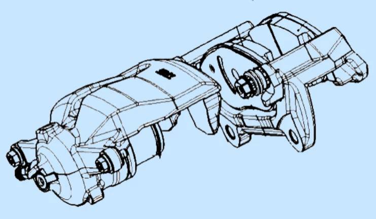
The automotive caliper body (Fig. 1) is a core component of the automotive braking system. Its structure significantly impacts vehicle safety.

Fig. 1 Automotive brake caliper housing
Manufacturers make the caliper body from high-strength materials to ensure stability and reliability under extreme braking conditions.
1. Compact Structure and High Strength Design
Designers typically use a compact structure for the caliper body to save space while maintaining mechanical strength.
The caliper body has two main parts: the housing and the piston. The housing holds the entire assembly while the piston pushes the pads to apply pressure to the disc.
2. Optimized Thermal Management and Corrosion Resistance
The caliper body’s internal structure is designed to facilitate heat diffusion. During braking, the heat generated must dissipate efficiently to prevent overheating and performance degradation. Therefore, manufacturers design caliper bodies with multiple ventilation channels for optimal thermal management.
Additionally, surface treatments are crucial. Designers often apply corrosion- and heat-resistant coatings to improve the caliper body’s durability in harsh environments.
3. Precision and Dimensional Tolerance Control
Precision and dimensional tolerance control are essential for the caliper body. These factors influence the fit between the caliper body and brake disc, affecting braking uniformity and stability.
Accurate design and processing ensure uniform braking force distribution, reduce vibration and noise, and enhance driving comfort.
4. Importance of Lightweight Design
The caliper body’s weight is a key design factor. Lightweight design reduces vehicle weight, improving fuel efficiency and handling.
Modern caliper body designs use lightweight materials and optimized structures to minimize weight while maintaining strength and function.
Table 1: Structural Characteristics of Automotive Caliper Bodies

Process Flow Design
In automotive caliper bodies’ CNC turning and milling machining process, the process flow design plays a key role in ensuring machining efficiency and quality.
This process includes several stages, from raw material selection to final product inspection. Each step requires careful planning.
A well-designed process flow can improve production efficiency and ensure high product quality and precision.
Selection and Preparation of Raw Materials
The first step is selecting and preparing raw materials. The materials must meet performance requirements such as strength, heat resistance, and corrosion resistance. This ensures the caliper body can withstand high temperatures and pressure during braking.
Before processing, strict quality inspections are performed to check the raw materials for defects. This avoids issues affecting the subsequent machining quality and final product performance.
1. Roughing Stage
The roughing stage follows. CNC milling machines remove most of the material allowance and form the basic shape of the caliper body. The goal is to remove excess material and reduce machining time quickly.
During roughing, leave enough machining allowance for finishing. Although the accuracy requirements are lower, maintaining the flatness of the machining and the initial shape is crucial.
2. Finishing Stage
The finishing stage is the most critical step. High-precision CNC machines perform fine machining to ensure the caliper body’s dimensional accuracy and surface finish meet design specifications.
Key areas of the caliper body, such as the brake pad contact surface and piston cavity, require precise machining. These areas directly affect braking performance. Strict dimensional control and surface treatment are also necessary to ensure the caliper body’s quality and reliability.
3. Heat Treatment and Surface Treatment
Heat treatment and surface treatment are essential steps to improve the caliper body’s mechanical properties. Heat treatment enhances hardness and strength, making the caliper body more wear-resistant and durable.
Surface treatment improves corrosion resistance, increasing the caliper body’s service life in harsh environments. It also enhances appearance and overall value.

Fig. 2 Caliper body heat treatment
4. Quality Inspection and Final Check
The caliper body undergoes a thorough quality inspection. This includes checking dimensional accuracy, surface roughness, and material properties. A meticulous inspection ensures that each caliper body meets design and safety standards. The inspection guarantees product performance and ensures the vehicle’s overall safety.
Selection of Machining Parameters
In the CNC turning and milling process of automotive caliper bodies, selecting appropriate machining parameters, such as cutting speed, feed, and depth of cut, is crucial. These parameters ensure machining efficiency and product quality.
Optimizing these parameters improves machining efficiency, extends tool life, and ensures accuracy. The following sections will explain how to select and adjust these parameters.
1. Cutting Speed Selection
Cutting speed is a core parameter in the machining process. It directly affects cutting temperature and cutting force.
A suitable cutting speed improves efficiency, reduces cutting force, lowers tool wear, and ensures higher machining accuracy. However, excessive cutting speed can cause overheating. Overheating affects the workpiece’s dimensional accuracy and surface integrity.
To avoid overheating, consider the following factors when selecting cutting speed:
Heat treatment status of the material: Different materials react differently to temperature. Adjust the cutting speed based on the material’s heat treatment status.
Heat resistance of the tool material: The tool’s heat resistance determines how much cutting heat it can handle. Choose a cutting speed based on the tool’s characteristics.
Machining accuracy requirements: Reduce the cutting speed for high accuracy to ensure quality.
2. Selection of Feed
Feed is another critical parameter that affects machining efficiency and surface quality. The correct feed ensures smooth machining and prevents tool overload or damage.
Too small a feed: This results in a good surface finish but reduces machining efficiency and increases costs.
Too large a feed can overload the tool, cause damage, and affect machining accuracy.
When choosing the feed rate, consider the material properties of the caliper body, the tool’s cutting performance, and the equipment’s stability. When machining harder materials, reduce the feed rate to minimize tool wear.
3. Selection of Cutting Depth
The depth of cut directly affects the material removal rate and tool load. Choosing the correct depth of cut improves the material removal rate, reduces machining time, and prevents tool overload.
A more significant depth of cut increases the material removal rate. However, it also raises the cutting force, which increases tool wear and may even cause tool breakage.
A smaller depth of cut reduces machining efficiency and wastes time.
Therefore, adjust the cutting depth based on these factors:
Workpiece material hardness: Harder materials need a shallower depth of cut to avoid damaging the tool.
Tool strength and machine rigidity: The strength and machine stability affect the cutting depth. Ensure the tool can handle the cutting load.
4. Parameter Adjustment in the Machining Stage
In the caliper body machining process, different stages require different machining parameters. Adjusting cutting parameters based on the stage improves processing results.
Roughing stage: Use higher cutting speeds and larger feeds to increase efficiency in roughing. Surface quality is not the main focus, as the goal is quickly removing material.
Finishing stage: Using lower cutting speeds and smaller feeds to enhance accuracy and surface quality. Higher precision is required, so more careful control is necessary.
Choosing the correct machining parameters boosts productivity, ensures machining quality, and improves the caliper body’s performance and reliability in the braking system.
Determination of Key Machining Processes
In CNC turning and milling the automobile caliper body, selecting the key machining processes is crucial for product quality and machining efficiency.
Accurate process selection impacts the shape, dimensional accuracy, machining efficiency, and cost control. The key processes and their importance in caliper body machining will be discussed in detail.
1. Overview of key machining processes
The machining process of the caliper body usually includes precision cutting, fine milling, and machining of critical holes and geometries.
Each of these processes performs a different function and is designed to ensure that the quality of the final product meets stringent technical requirements.
The most critical part of these processes is to ensure the accuracy of the critical dimensions and shapes of the caliper body, especially the piston chambers, the flatness of the brake pad contact surfaces and the,e accuracy of the mounting holes.
These dimensions and shapes are crucial to the normal function and braking performance of the caliper body, which is directly related to the safety and driving performance of the whole vehicle.
2 . Precision Cutting Process
The precision cutting process begins the machining of the caliper body. It creates the main geometry and contour of the workpiece.
At this stage, the shape and general dimensions of the caliper body are formed. However, some machining allowance is still left for fine machining in later stages.
The machining accuracy at this stage directly impacts the results of the subsequent processes.
Errors at this stage can affect the quality and efficiency of the entire machining process. Therefore, we must strictly control the accuracy of the machining to ensure the final workpiece meets design requirements.
3. Fine Milling Process
Fine milling is the core step in machining the caliper body. It ensures precise sizing and improves the surface finish.
During this stage, high-precision CNC machine tools remove the remaining machining allowance. This ensures the workpiece’s dimensions and tolerances meet the design specifications.
Fine milling requires high-precision equipment. It also demands skilled operators.
Any minor operational errors or equipment issues can cause product quality fluctuations and affect overall braking performance.
4. Key Holes and Special Geometric Shapes Machining
Accurate machining of keyhole and unique geometries is crucial during caliper body machining.
These parts have high precision requirements and complex shapes. They directly impact the caliper body’s functionality and structural stability.
We must ensure the dimensional and positional accuracy of these areas. They determine how well the caliper body fits with other automotive components.
Errors in the location or shape of these holes may cause the caliper body not to fit or function correctly, affecting the braking system’s overall performance.
Table 2 Fixture design for caliper body machining

The proposal and selection of the design program
1. Importance of Fixture Design
In the machining process of an automotive caliper body, selecting and proposing the right fixture design is crucial. This decision directly impacts machining efficiency, accuracy, and cost.
The fixture design must meet the technical requirements of machining. It should also balance the economy and ease of operation.
The design team must analyze the machining requirements of the caliper body. These include machining accuracy, batch size, workpiece material, and shape.
2. Design Proposal
The design proposal combines innovation and technical knowledge to ensure the fixture meets specific machining requirements.
The design team must consider the stability and reliability of the fixture. It must effectively support and hold the caliper body workpiece.
The fixtures should also be easy to operate. This will reduce clamping and adjustment times, increasing productivity.
The design team must also protect the workpiece. They should avoid damage during the machining process.
3. Selection of Design Options
The design selection phase presents several possible fixture designs. The team compares and selects these options based on specific evaluation criteria.
The criteria include cost-effectiveness, design complexity, machining accuracy, fixture reliability, ease of maintenance, and other factors.
(1) Cost-effectiveness
Cost-effectiveness is one of the most critical factors in selecting fixture design solutions. The design should meet technical requirements and ensure economic viability.
The design must consider material, manufacturing, and operating costs to ensure the overall cost remains within an acceptable range.
(2) Design Complexity
The complexity of the design is a key evaluation factor. A complex design can increase manufacturing difficulties and later lead to higher maintenance costs.
Therefore, the ideal fixture design should be as simple as possible. It should be easy to manufacture and maintain while still ensuring its functionality.
(3) Machining Accuracy
Machining accuracy is the core requirement of fixture design. The design must keep the workpiece stable during the machining process. It must ensure positional accuracy to maintain processing quality.
(4) Fixture Reliability and Maintenance
Fixture reliability and ease of maintenance are also crucial in the selection criteria. The design should ensure stability and durability during long-term use. It should also allow easy routine maintenance and adjustments, minimizing equipment downtime and improving productivity.
The design team can choose the most suitable fixture design by evaluating all these factors. This design will meet the technical requirements while providing economic and operational benefits, resulting in an efficient and reliable automotive caliper body machining solution.
Structural design and calculation
1. Positioning Program and Positioning Element Design
In designing fixtures for automotive caliper body machining, the designer must focus on positioning schemes and elements to ensure machining accuracy.
The designer’s goal is to control the workpiece’s position during machining precisely. This ensures the accuracy of the machined dimensions and shapes.
The designer must consider several factors for efficient and accurate machining to achieve this.
(1) Positioning Program Design
The designer begins by considering the workpiece’s specific characteristics, such as shape, size, and machined surface.
The main goal is to keep the workpiece stable during machining and prevent errors from workpiece displacement. The positioning solution should also be easy to clamp and unclamp, improving productivity.
An effective positioning solution improves machining efficiency and quality while reducing errors. It ensures machining accuracy, reduces machine and tool wear, and lowers production costs.
(2) Positioning Element Design
Positioning elements play a key role in ensuring precise workpiece positioning. Common elements include pins, blocks, brackets, and collets.
The designer must consider how these elements contact the workpiece to prevent damage during machining.
Positioning elements must also be strong and rigid enough to withstand external forces during machining.
Adjustability and versatility are important factors in designing positioning elements. Adjustability allows the element to fit different sizes or shapes of workpieces, increasing fixture flexibility.
Versatility helps reduce costs and expands the fixture’s applications. For example, using standard collets and pins lowers customization costs and boosts productivity.
The accuracy of the positioning elements is critical. The designer must ensure these elements are manufactured and assembled with precise accuracy. Tight quality control during design, manufacturing, and inspection prevents small errors from affecting overall machining accuracy.
2. Selection and Design of Clamping Mechanism
In the design of automotive caliper body machining fixtures, selecting and designing the clamping mechanism is crucial. It directly affects the workpiece’s stability during machining. Therefore, designers must carefully plan it.
(1) Basic Requirements of the Clamping Mechanism
The main task of the clamping mechanism is to fix the workpiece securely without causing damage. Besides ensuring stability, the design must consider operational convenience and processing efficiency.
The material, shape, and size of the workpiece and the forces it will endure during processing influence the selection of the clamping mechanism.
(2) Uniform Distribution of Clamping Force
The clamping force must be evenly distributed when designing the clamping mechanism. This helps maintain the workpiece’s stability during machining and prevents deformation due to excessive clamping force.
In particular, when machining complex shapes or large workpieces, evenly distributed clamping force prevents local stress concentrations.
(3) Selection of Clamping Device Type
The clamping device can be manual, hydraulic, or pneumatic. Manual devices are simple and economical, making them ideal for small-batch production.
Hydraulic and pneumatic devices are more suited to high-volume, high-precision production. They provide a more uniform and controllable clamping force, improving processing efficiency and product quality.
(4) Ease of Operation and Maintenance
The clamping mechanism design must also prioritize ease of operation. An easy-to-operate system reduces clamping and unloading time, boosting productivity.
Additionally, the design must consider the ease of adjusting and maintaining the clamping mechanism. This ensures it can adapt to different workpieces and processing needs.
(5) Safety and Reliability
Finally, the design must ensure safety. A well-designed clamping mechanism prevents accidental loosening or clamping failure, protecting both operators and equipment.
This is particularly critical in high-precision machining, where clamping errors can significantly reduce machining quality.
3. Design of Forcing Mechanism
The fixture’s design for machining the automotive caliper body heavily depends on the forcing mechanism. It ensures the workpiece stays in the correct and stable position during machining. This improves machining efficiency and safety. Below are the key points on the design requirements and considerations for the forcing mechanism.
(1) Role and Importance of the Forcing Mechanism
The forcing mechanism’s main function is to prevent the workpiece from shifting or rotating during machining. In precision machining, even a small positional deviation can lead to defective parts. Therefore, the design must fix the workpiece accurately and effectively to ensure machining precision.
(2) Key Elements for Designing a Forcing Mechanism
The design typically includes positioning pins, pressure plates, and stops. The layout and size of these components must match the shape of the workpiece and machining needs. For example, locating pins sets the initial position of the workpiece. Platens and stops maintain their stability during machining.
The design must also consider the contact pressure on the workpiece. Too much pressure can deform or damage the workpiece, especially for thin-walled or soft materials. Therefore, the design must control the contact pressure to secure the workpiece without causing harm.
(3) Operational Convenience and Safety
The forcing mechanism design should ensure easy operation. Operators must be able to clamp and unload the workpiece quickly and safely. Avoiding hazards during fixture operation is critical for improving productivity and operator safety.
(4) Durability and Reliability
The forcing mechanism faces continuous mechanical pressure and wear during machining. Therefore, the design must prioritize durability and reliability. Using strong materials and proper reinforcement ensures stability and reduces long-term maintenance costs.
A well-designed forcing mechanism will significantly improve the accuracy and efficiency of caliper body machining. This will positively impact the performance and safety of the entire automotive braking system.
4. Fixture assembly and debugging
(1) Fixture Assembly Process
In automotive caliper body machining, fixture assembly and debugging are key to ensuring accuracy and efficiency.
First, the fixture must be assembled by combining various components precisely. These components typically include positioning elements, clamping mechanisms, forcing mechanisms, and other supporting and connecting parts.
During assembly, ensure that the position and orientation of each component are precise and match the design drawings. Tighten all components to prevent loosening during machining.

Fig. 3 Flow chart of fixture assembly
(2) Fixture Debugging
After assembly, move the fixture to the debugging stage. The goal is to verify its function and ensure it can accurately locate and fix the workpiece.
During commissioning, the operator will perform trial assembly checks to confirm whether the fixture’s positioning and clamping meet the requirements. Adjust the fixture if the positioning is inaccurate or the clamping forces are uneven.
Also, check the fixture’s adaptability. Some parts of the fixture may need adjustment for workpieces of different shapes or sizes to accommodate various machining needs.
The fixture’s operability is equally essential. The operator should easily clamp and unload the workpiece. The fixture should operate safely and reliably.
(3) Precision Inspection and Adjustment
Another key task during commissioning is ensuring the fixture’s accuracy. Use precision measuring tools, such as micrometers or a coordinate measuring machine, to check each key part of the fixture. Ensure that the fixture meets the design accuracy standards. If deviations occur, carefully adjust the fixture until it meets the required accuracy.
The following figure shows the three-dimensional diagram of the fixture and its positioning effect during debugging. The fixture can efficiently and safely support and position the workpiece through accurate assembly and debugging. This ensures the accuracy and quality of the automotive caliper body machining process.

Fig. 4 Three-dimensional drawing of fixture

Fig. 5 3D drawing of positioning effect
Conclusion
We studied the automotive caliper body CNC turning and milling machining process in depth. We successfully optimized the machining parameters, established the key machining processes, and designed an efficient and stable fixture.
Practical application shows that the new process and fixture design improve processing efficiency and product quality. They also ensure the machining accuracy of the caliper body, which enhances the safety performance of the entire braking system.
The research results provide valuable references for the precision machining of similar complex parts. They also contribute to improving the technical level of the automobile manufacturing industry.

Solomon Yang is a manufacturing industry professional with extensive experience in electronic, mechanical, and industrial component manufacturing. Having held various positions in American and Taiwanese manufacturing companies, he has developed a comprehensive understanding of manufacturing processes, production management, quality control, and global supply chain operations.
With expertise in business development, sales operations, international trade, customer relationship management, and engineering project support, Solomon bridges technical knowledge with commercial strategy to deliver innovative and cost-effective manufacturing solutions. He is passionate about advanced manufacturing technologies, process improvement, and continuous professional growth, with a strong commitment to creating value for customers and partners worldwide.

