
Ti6Al4V titanium alloy is known for its high strength, low density, heat resistance, and corrosion resistance, making it widely used in aerospace, automotive, and medical fields. Due to its hardness of up to 320HBW and tensile strength of at least 1200MPa, it presents challenges such as increased crushing, pulling out, and debonding during machining. Studying its cutting and machining processes is crucial for improving efficiency and quality.
Ti6Al4V performance analysis
The material’s chemical composition, metallographic organization, and mechanical properties mainly determine Ti6Al4V’s cutting and machining difficulty. Table 1 shows its chemical composition, and Table 2 shows its mechanical properties.
Table 1 Ti6Al4V titanium alloy chemical composition (mass fraction)(%)

Table 2 Ti6Al4V titanium alloy mechanical properties

Introduction to thin-walled magazine parts
Thin-walled magazine parts are shown in Figure 1, and the part size is shown in Figure 2. The part belongs to the large diameter thin-walled structure, mainly composed of a thin-walled straight cylinder, multiple flanges in the outer diameter, beveled surfaces, and grooves. The material of the part is Ti6Al4V titanium alloy, and its key dimensions include:
Base end face: end face four and inside diameter (2013.7±0.5)mm;
Maximum outer diameter: (2108.7 ± 0.5) mm;
Thinnest wall thickness: (6±0.5)mm;
Height: (678±0.5)mm;
Surface roughness: Ra≤3.2μm;
Flatness: ≤0.2mm;
Roundness: ≤0.5mm.
The inner and outer diameters of the part have complex cross-sections, which makes it more difficult to turn the CNC. Due to the thin-walled structure’s susceptibility to deformation from internal and external forces, coupled with the unique cutting characteristics of titanium alloys—such as their high hardness and cutting forces—there is a higher likelihood of tool wear and unstable machining accuracy during processing.
Analysis of machining difficulties
1. Deformation of thin-walled structure
Given the part’s thin wall thickness of 6mm ± 0.5mm, it is susceptible to deformation during machining, particularly due to the uneven cutting forces encountered. This is especially problematic in the turning process, where the poor rigidity of the thin-walled part can lead to uneven deformation, ultimately affecting machining accuracy.
2. Complex section of internal and external diameter
Given that the inner and outer diameters of the parts feature complex-shaped sections, the tool often struggles to adapt to the non-circular contours during machining. This can lead to tool vibration and unstable machining accuracy. Consequently, precise control of the cutting parameters and tool path becomes essential to ensure stability and precision.
3. Machining characteristics of titanium alloy
Although titanium alloy material is highly strong and tough, the cutting process is prone to high cutting forces and temperatures. These lead to faster tool wear, potentially affecting the surface quality of the parts and machining efficiency. Moreover, excessive cutting forces may even cause tool chipping for thin-walled parts.
4. High precision requirements
Given the high precision requirements of the parts, such as flatness ≤ 0.2mm, roundness ≤ 0.5mm, and surface roughness Ra ≤ 3.2μm, it is crucial to carefully control the cutting depth and feed rate during the machining process. This is especially important during the fine-tuning stage, where even the smallest error can significantly impact the final product’s quality.
5. Cooling and cutting fluid management
Given the high-temperature characteristics of titanium alloys, the cutting temperature during machining is elevated. Therefore, it is crucial to carefully select the appropriate coolant and cutting fluids, ensuring effective cooling to prevent overheating, which could lead to material deformation or tool damage.

Figure 1 parts three-dimensional model

Figure 2 part size
Processing technology plan
Table 3 shows the development of the machining process program by analyzing the parts’ structure and processing difficulties.
Table 3 machining process program


Figure 3 Specialized tooling
Implementation of the technology program
1. Tool selection
Given that the surface of the titanium alloy blank is hard after heat treatment. It exhibits a large diameter and oval shape. The turning process is characterized by high cutting forces, often resulting in tool chipping. Therefore, special considerations must be made to optimize the turning parameters and ensure tool longevity. For the needs of different processing stages, the selection of suitable tools is the key to ensure smooth processing:
Rough turning machining: choose YG8 carbide tools with strong impact resistance, which can effectively cope with the higher cutting force.
For semi-finish turning and finish turning processing, use CNMG160612-GJVP10RT and RPMT10T3MOE-JS VP15TF coated carbide inserts, which are suitable for processing with higher precision requirements.
2. CNC program for fine-turning parts
Given the complexity of the part’s geometry and the analysis of its machining challenges and process plan, computer-aided manufacturing (CAM) for programming is necessary. The main steps are as follows.
(1) processing parts and process analysis
Confirm the part’s size, tolerance, and accuracy requirements.
Determine the machining process’s feed route, jigs and fixtures, gauges, and tools.
Determine the programming origin and coordinate system to ensure the program is correct.
(2) Modeling of machined parts
Establish a three-dimensional model of the part using computer-aided design (CAD) software to provide accurate data support for subsequent processing.
(3) Input of machining parameters
Input parameters include machine tool model, blank size, tool type, and cutting amount.
Configuring machining conditions requires considering various factors, including the safety plane, tool trajectory, feed and withdrawal modes, and cooling mode.
(4) Tool trajectory generation and refinement
Based on the geometric and process information, the system automatically performs the calculations and organizes the tool path. However, if the tool path is unreasonable, it can be optimized through human-computer interaction.
(5) Trajectory simulation and first trial machining
Import the program into the air operation equipment to verify the tool trajectory’s correctness and reasonableness.
Verify the program’s machining accuracy through the first trial machining, find potential problems, and make corrections.
(6) Subsequent program processing
Convert the tool trajectory file into a program the CNC lathe can run accurately. Precision turns the small end and external circle, as shown in Figure 4.

Figure 4 Precision turning small end and external roun.d
Taking the finetuning off the f external groove one as an example, choose the ball groove tool with a width of 6mm and a tip of R3.0mm. The program is as follows.
N100
T0000
G00 X2400.Z-70
X2111.6
S8 MO3
MO8
G01 X2058.2 F0.3
G03 X2054.983 Z-69.188 CR=2.F0.15
G01 X2059.809 Z-67.406 F0.5
G00 X2116.42
Z2.657
X2100.772
G01 X2110.Z-1.957 F0.3
Z-14.043
X2106.085 Z-16.
X2058.2
G02 X2054.2 Z-18.CR=2.F0.15
G01 Z-68.F0.3
G02 X2055.534 Z-69.491 CR=2.F0.15
G01 X2059.533 Z-67.254 F0.5
G00 X2400.
Z50.
M09
MO5
M00
A 50° sharp cutter with a tip of R1.2 mm is used for small-end fine turning of an internal circle, and the program is as follows.
N160
TO000
G00 X1600.Z50.
X2047.874
Z3.184
S8 MO3
M08
G01 X2039.7 Z-.903 F0.3
Z-226.202
G03 X2038.553 Z-230.282 CR=14.8
G01 X2032.884Z-240.168
G03 X2029.377 Z-244.054 CR=14.8
G01 X2029.Z-244.35
Z-271.328
X2029.542 Z-271.66
G03 X2036.222 Z-280.649 CR=14.8
G01 X2041.219 Z-377.378
G03 X2039.722 Z-382.422 CR=14.8
G01 X2039.6 Z-382.606
Z-411.1
G00 X1600.
Z50.
M09
MO5
M00
M30
Precision turning of the big end and outer circle is shown in Fig. 5.

Figure 5: Precision turning large end and outer circle
To finish turning the outer circle, choose the ball groove cutter with a width of 6mm and a tip of R3.0mm. The program is as follows.
N170
T2D2
G0X2140
G00 Z-238
G00 X2128.000
M3S10
G01 Z-93.657 F0.4
G01 X2124.085 Z-91.700
G01 X2073.000
G03 X2069.000Z-89.700 CR=2.000
G01 Z-88.7
G0X2140
G00 Z-29
G00 X2134.700
G95 G01 Z-63.643
G01 X2130.785 Z-65.600
G01 X2073.000
G02 X2069.000 Z-67.600 CR=2.000
G01 Z-89.5
G0X2140
G00 Z-32.493
G00 X2135.371
G95 G01 X2132.543 Z-31.079
G02 X2128.300 Z-30.200 CR=3.000
G01 X2065.268
G03 X2061.508 Z-28.882 CR=2.000
G01 X2042.121 Z-2.176
G02 X2040.724 Z-1.079 CR=3.000
G01 X2040.324 Z-0.879
G02 X2036.081 Z-0.000 CR=3.000
G01 X2015
G0Z82M9
M5
X2280
M0
The following program selects a ball groove cutter with a width of 6mm and a tip of R3.0mm for large-end fine turning of an internal circle.
N180
T2D2
G00 X2030.650
Z2.5
M3S10
G1 Z0.907 F0.4
G01 X2026.820 Z-1.007
G01 X2043.000 Z-29.119
G01 Z-103.900
G02 X2048.232 Z-112.113 CR=14.200
G03 X2050.000 Z-114.889 CR=4.800
G01 Z-140.661
G01 X2042.600 Z-174.261
G01 Z-254.236
G03 X2035.200 Z-264.025 CR=14.800
G0X2010M9
M5
Z50
M30
3. Cutting parameters
Table 4 shows the tool’s selected cutting parameters based on the part material, dimensional accuracy, and surface roughness requirements, combined with the recommended cutting values in the tool manual.
Table 4 Cutting parameters of the tool

Machining verification
Through the in-depth analysis of titanium alloy magazine CNC turning machining, the appropriate process route, CNC program, and cutting parameters were selected, and machining verification was carried out. The specific machining strategies are as follows:
1. Rough turning machining strategy
In the rough turning machining stage, the following cutting strategies are used quickly remove excess material and reduce machining time:
Low to medium speed: Due to the cutting characteristics of titanium alloys, low speed helps to reduce cutting forces and temperatures and reduces tool wear.
Faster feed: A faster feed rate can effectively increase the material removal rate and shorten the machining cycle time while avoiding thermal deformation caused by high cutting temperatures.
Larger depth of cut: using a larger cut can quickly remove large pieces of material and reduce machining time.
2. Precision turning machining strategy
The main goal of the Chinese stage is to ensure the accuracy and surface quality of the parts, so the following cutting methods are used:
Higher RPM: Increase the cutting speed to achieve a better surface finish while reducing the effect of cutting forces on thin-walled structures.
Slower feed: Slower feed rates help to improve machining accuracy and reduce tool and workpiece vibration.
Smaller depth of cut: A smaller cut can reduce the cutting force, reduce the deformation on thin-walled parts, and ensure machining accuracy.
The reasonable combination of the above strategies ensures the machining accuracy and surface quality of the titanium alloy magazine parts.
3. Machining results and size inspection
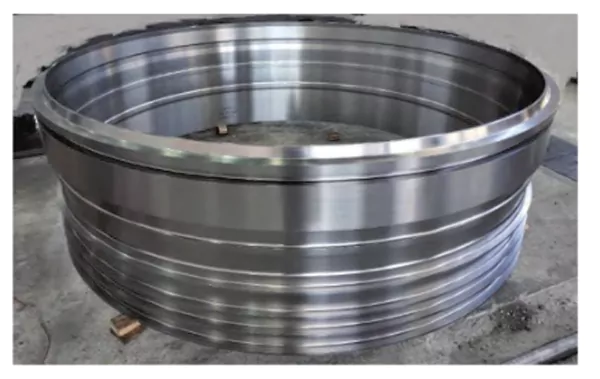
After machining verification, the titanium alloy magazine parts are completed, and all the machining steps are executed strictly with the set process route and parameters. The key dimensional inspection records of the machined titanium alloy magazine are shown in Table 5, and the finished parts are shown in Figure 6.
Table 5 Key dimensions of titanium alloy magazine(Unit: mm)


Figure 6 Finished parts
Conclusion
This paper analyzes the problems and difficulties in the turning process of large-diameter titanium alloy magazines, prepares a reasonable machining process and CNC program, and selects suitable tools and cutting parameters, which makes the parts’ turning process smooth. Because of the parts of larger diameter, thinner wall thickness, the size of the high precision requirements, the design of a special tooling fixture to ensure the quality of the product, verified by the actual processing, a better solution to the large diameter titanium alloy magazine CNC turning machining problems.

Solomon Yang is a manufacturing industry professional with extensive experience in electronic, mechanical, and industrial component manufacturing. Having held various positions in American and Taiwanese manufacturing companies, he has developed a comprehensive understanding of manufacturing processes, production management, quality control, and global supply chain operations.
With expertise in business development, sales operations, international trade, customer relationship management, and engineering project support, Solomon bridges technical knowledge with commercial strategy to deliver innovative and cost-effective manufacturing solutions. He is passionate about advanced manufacturing technologies, process improvement, and continuous professional growth, with a strong commitment to creating value for customers and partners worldwide.

