

Quick Answer
CNC machining tolerance is the permissible variation in a part’s dimension from its nominal value. Standard CNC tolerances are typically ±0.05 mm (±0.002 in) for general features, while precision CNC machining can achieve much tighter tolerances for critical components.
Tolerances are where engineering drawings turn into manufacturing costs. A single over-specified tolerance on a non-critical feature can double the price of a part, delay delivery by days, and create inspection bottlenecks that slow your supply chain for months.
Yet under-specified tolerances cause assembly failures, field returns, and reputation damage that cost far more.
Understanding CNC machining tolerances, what they mean, how they are classified, what modern machines can actually hold, and how to specify them intelligently, is one of the highest-value skills any mechanical engineer or product designer can develop. This guide covers all of it.
What Is Machining Tolerance?
A tolerance is the total permissible variation in a dimension. If a shaft is specified as 25.00mm with a tolerance of ±0.05mm, any shaft measuring between 24.95mm and 25.05mm is an acceptable part. The total tolerance band here is 0.10mm.
Tolerances exist because no manufacturing process is perfectly repeatable. Every tool deflects under cutting force. Every workpiece expands and contracts with temperature changes. Every fixture introduces small but real positioning errors. Tolerances define the envelope within which those unavoidable variations are acceptable for the part to function correctly.
The relationship between tolerance and function is everything. A bearing bore that is 0.02mm oversized will have measurable radial play. A clearance hole that is 0.5mm oversized will still accept a bolt just fine. The engineering judgment involved is knowing the difference.
Understanding tolerance begins with understanding the CNC processes that hold them. Learn more about our capabilities: Application and Optimization of CNC Technology in Efficient Precision Machining.
Types of Tolerances in CNC Machining
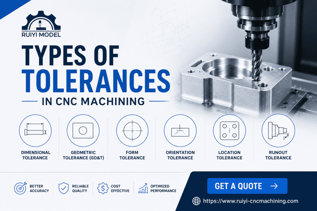
Dimensional Tolerances
These control linear dimensions: lengths, widths, heights, diameters, depths. They are expressed as bilateral (±0.05mm either side of nominal) or unilateral (+0.00 / -0.10mm, allowing deviation in only one direction).
Geometric Tolerances
Geometric tolerances control the shape, orientation, and location of features independent of their size. These are specified using GD&T symbols and include flatness, cylindricity, perpendicularity, parallelism, true position, runout, and concentricity.
Surface Finish Tolerances
Surface roughness (Ra) and surface texture specifications control the microscopic topography of machined surfaces. Typical as-machined CNC surfaces have Ra values of 1.6 to 3.2 micrometers. Polished or ground surfaces can achieve Ra 0.1 to 0.4 micrometers.
Thread Tolerances
Threaded features follow standard tolerance classes defined by ISO (6H/6g for metric) or ANSI/ASME (2B/2A for unified inch threads). These classes define the permissible pitch diameter variation for fit, from loose (class 1) to precision (class 3).
For advanced guidance on threading and tolerance, read: Research on Thread CNC Milling Processing Technology.
ISO 2768 and ASME Y14.5 Standards
ISO 2768: General Tolerances
ISO 2768 defines general tolerance grades for linear dimensions and geometric features on drawings that do not carry individual tolerance callouts. It has four tolerance classes:
| Class | Symbol | Description | Typical Use |
| Fine | f | Tighter than medium | Precision mechanisms |
| Medium | m | Standard workshop accuracy | Most machined parts (default) |
| Coarse | c | For less critical features | Castings, rough machining |
| Very Coarse | v | Loosest class | Semi-finished or rough stock |
For a 30mm nominal dimension under ISO 2768-m (medium), the linear tolerance is ±0.2mm. Under ISO 2768-f (fine), it is ±0.1mm. These apply to dimensions not individually toleranced on the drawing.
ISO 2768 Linear Tolerances by Dimension Range
| Nominal Range | Fine (f) | Medium (m) | Coarse (c) |
| 0.5 to 3mm | ±0.05mm | ±0.1mm | ±0.2mm |
| 3 to 30mm | ±0.1mm | ±0.2mm | ±0.5mm |
| 30 to 120mm | ±0.15mm | ±0.3mm | ±0.8mm |
| 120 to 400mm | ±0.2mm | ±0.5mm | ±1.2mm |
| 400 to 1000mm | ±0.3mm | ±0.8mm | ±2.0mm |
ASME Y14.5: GD&T Standard
ASME Y14.5 (most recent edition: 2018) is the dominant American standard for Geometric Dimensioning and Tolerancing. It defines a symbolic language for specifying not just the size of features but their shape, orientation, location, and runout relative to datums. GD&T is more precise and manufacturing-friendly than traditional plus/minus dimensioning for complex functional requirements.
💡 DID YOU KNOW?
ISO 2768-m is the most commonly referenced general tolerance standard in international CNC machining. If your drawing does not specify a general tolerance standard, ask your supplier which standard they apply by default. Assumptions here can lead to costly manufacturing disputes and rework. For the full ISO 2768 specification document, see the ISO online browsing platform: ISO.org.
Typical CNC Tolerance Capabilities by Process
| Process | Standard Tolerance | Precision Tolerance | Notes |
| CNC Milling (3-axis) | ±0.05mm | ±0.01mm | Location and size |
| CNC Milling (5-axis) | ±0.05mm | ±0.01mm | Complex geometry |
| CNC Turning | ±0.05mm | ±0.005mm | Diameters, runout |
| CNC Grinding | ±0.005mm | ±0.001mm | Post-machining process |
| Boring | ±0.01mm | ±0.002mm | Bore diameter and roundness |
| Reaming | H7 fit (±0.015 to 0.030mm) | H6 fit | Hole fitting |
| Wire EDM | ±0.01mm | ±0.002mm | Complex profiles, hardened material |
| Jig Boring | ±0.005mm | ±0.001mm | Precision location of holes |
These figures represent what well-maintained machines with qualified operators can achieve under controlled conditions. Real-world tolerances depend on part geometry, material, setup complexity, and environmental temperature control of the machining facility.
For a real-world machining case study showing how tolerances are managed on complex parts, read: Processing Case: CNC Machining Process Analysis and Testing of Precision Special-Shaped Parts.
GD&T: Geometric Dimensioning and Tolerancing
GD&T moves beyond simple plus/minus dimensions to define exactly what shape, orientation, and location a feature must have to function correctly. It is the language of precision manufacturing, and using it correctly eliminates the ambiguity that causes scrap and rework.
The 14 GD&T Characteristics
| Category | Characteristic | Symbol |
| Form | Flatness | △ |
| Form | Straightness | — |
| Form | Circularity | ○ |
| Form | Cylindricity | ◇ |
| Orientation | Perpendicularity | ⊥ |
| Orientation | Parallelism | // |
| Orientation | Angularity | ∠ |
| Location | True Position | ⊕ |
| Location | Concentricity | ◎ |
| Location | Symmetry | ≡ |
| Profile | Profile of a Line | ⌒ |
| Profile | Profile of a Surface | ⌣ |
| Runout | Circular Runout | ↗ |
| Runout | Total Runout | ↗↗ |
Why True Position Matters More Than Plus/Minus for Hole Patterns
When you have a bolt circle with four holes, traditional plus/minus dimensioning creates a square tolerance zone for each hole center. GD&T true position creates a cylindrical tolerance zone. For the same assembly function, a cylindrical zone provides 57% more usable tolerance area than a square zone, meaning fewer rejected parts and lower cost without compromising function. This is one of the most concrete economic benefits of switching to GD&T.
How Tolerance Affects Cost and Lead Time
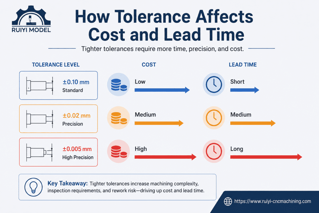
The relationship between tolerance and cost is not linear. It is exponential. Moving from ±0.1mm to ±0.05mm might increase cost by 20%. Moving from ±0.05mm to ±0.01mm might increase cost by 100 to 200%. Moving from ±0.01mm to ±0.005mm may require grinding operations, temperature-controlled inspection, and specialized fixturing, multiplying cost several times over.
| Tolerance Range | Relative Cost | What It Requires |
| ±0.1mm to ±0.5mm | Baseline (1x) | Standard CNC setup, no special inspection |
| ±0.05mm | 1.2x to 1.5x | Careful setup, standard inspection |
| ±0.02mm | 1.5x to 2x | Temperature stabilization, calibrated tooling |
| ±0.01mm | 2x to 3x | CMM inspection, precision fixturing |
| ±0.005mm | 3x to 5x | Often requires grinding, SPC, CMM full report |
| <±0.005mm | 5x to 10x+ | Specialty processes, air gauging, lapping |
See how precision machining processes are optimized to meet demanding tolerance requirements: How to Improve Product Precision by Optimizing Machining Processes.
PRO TIP
The 80/20 rule applies to tolerances. Roughly 80% of a typical machined part’s features can accept ISO 2768-m (medium) tolerances. The remaining 20% that require tighter control should be identified through functional analysis, not habit or excessive caution. Spend your tolerance budget on the features that truly affect performance, fit, and function.
Best Practices for Specifying Tolerances
1. Start with Functional Analysis
For every feature on your drawing, ask: “What happens if this dimension is at its maximum allowable deviation?” If the answer is “nothing,” loosen the tolerance. If the answer is “assembly failure,” tighten it with precision. Let function drive every specification.
2. Use GD&T for Critical Features
Plus/minus dimensioning for location tolerances of hole patterns is ambiguous and wasteful. GD&T true position gives more usable tolerance for the same functional requirement. Learn the five most common GD&T symbols (flatness, true position, perpendicularity, cylindricity, runout) and your drawings will immediately become more manufacturable.
3. Always Specify a General Tolerance Standard
Every drawing should carry a note specifying the general tolerance standard: “Unless otherwise specified: ISO 2768-m” or “Untoleranced dimensions per ASME Y14.5.” Without this, your supplier applies their own interpretation, and disputes follow.
4. Understand Material Behavior
Aluminum expands approximately 23 micrometers per meter per degree Celsius. A 100mm aluminum bore measured at 20°C in an air-conditioned shop will be 2.3 micrometers larger at 30°C. For tolerances tighter than ±0.01mm, dimensional measurement temperature becomes a specification, not an afterthought.
5. Design Features for Inspectability
A tolerance you specify but cannot measure is meaningless. Before adding a tight tolerance, confirm that your supplier has the inspection equipment to verify it: CMM, laser tracker, air gauge, or optical comparator as appropriate. Ask for the inspection method with your quote.
6. Communicate Early with Your Machining Supplier
Share your drawing in DFM review before finalizing it. Experienced CNC machinists will immediately identify tolerances that are either impossible to achieve with standard setups, or that add cost without contributing to function. This conversation costs nothing and frequently reduces part cost by 15 to 30%.
For our comprehensive approach to DFM and quality control, see: CNC Machining Process Quality Control: Key Aspects of Research.
Common Mistakes That Engineers Make with Tolerances
1: OVER-TOLERANCING THE ENTIRE DRAWING
Specifying tight tolerances on every feature “just to be safe” is one of the most expensive mistakes in engineering drawings. It signals inexperience to suppliers and directly inflates quotes. Apply tight tolerances surgically, only where function demands it.
2: TOLERANCE STACK-UP ANALYSIS NEGLECTED
Individual features can each be within tolerance, yet the assembled system fails because individual tolerances stack in an unfavorable direction. Worst-case tolerance stack-up analysis should be completed before finalizing any assembly-critical dimension chain.
3: SPECIFYING TOLERANCES WITHOUT VERIFYING INSPECTABILITY
A ±0.003mm tolerance on a deep internal bore may be functionally necessary but physically impossible to measure with standard equipment. If your supplier cannot measure it, they cannot certify it. Always confirm measurement capability before specifying extreme tolerances.
4: FORGETTING THREAD FIT CLASS
Unspecified thread tolerances default to different classes at different suppliers. Always specify the thread fit class explicitly: M8x1.25 – 6H for internal threads, M8x1.25 – 6g for external threads. For precision applications requiring minimal clearance, specify class 5H/5g or 4H/4g and confirm your supplier can hold it.
| EXPERT INSIGHT – “The drawings we receive from experienced engineers tell a story. When we see tight tolerances on just the features that functionally require them, and ISO 2768-m on everything else, we know we are working with someone who understands manufacturing. The quotes are cleaner, the parts are right the first time, and inspections move faster. When we receive drawings where every dimension has a tight bilateral tolerance regardless of function, the quote goes up significantly and we initiate a DFM conversation before proceeding. The tolerance conversation is always worth having upfront.”— RuiYi CNC Machining Engineering Team |
Key Takeaways
- Standard CNC machining tolerances are typically ±0.05mm; precision machining can achieve ±0.005mm or tighter with appropriate processes.
- ISO 2768-m is the most common general tolerance standard for CNC machined parts. Always state it explicitly on your drawing.
- Tolerance cost is exponential, not linear. Each tenfold improvement in tolerance can multiply part cost by two to five times.
- GD&T true position provides approximately 57% more usable tolerance than equivalent plus/minus tolerancing for hole patterns, helping reduce costs without compromising function.
- Apply tight tolerances only to features where functional analysis proves they are necessary.
- Tolerance stack-up analysis is essential for any dimension chain involving more than two parts.
- Discuss tolerance requirements with your CNC supplier during the DFM review before finalizing drawings.
Conclusion:
CNC machining tolerances determine the acceptable variation in part dimensions and directly affect quality, cost, and lead time. By applying the right tolerance standards, such as ISO 2768 and ASME Y14.5, engineers can ensure accurate manufacturing, efficient inspection, and cost-effective production.
Frequently Asked Questions
What is the standard tolerance for CNC machining?
The most common general CNC machining tolerance is ±0.1 mm to ±0.2 mm based on ISO 2768-m. Many machine shops can also achieve ±0.05 mm for standard machined features.
What is the tightest tolerance achievable with CNC machining?
High-precision CNC machining can achieve tolerances as tight as ±0.001 mm to ±0.005 mm under controlled conditions, although tighter tolerances increase production costs.
What is the difference between bilateral and unilateral tolerance?
Bilateral tolerance allows variation in both directions from a nominal dimension, while unilateral tolerance allows variation in only one direction.
What is ISO 2768?
ISO 2768 is an international standard that defines general tolerances for dimensions and geometric features not individually specified on engineering drawings.
How does surface finish relate to tolerance?
Surface finish and dimensional tolerance are separate specifications, but smoother surface finishes are often required to achieve tighter tolerances.
Do CNC tolerances differ between milling and turning?
Yes. CNC turning generally achieves tighter tolerances on round features, while CNC milling typically holds ±0.05 mm for standard linear features.

Solomon Yang is a manufacturing industry professional with extensive experience in electronic, mechanical, and industrial component manufacturing. Having held various positions in American and Taiwanese manufacturing companies, he has developed a comprehensive understanding of manufacturing processes, production management, quality control, and global supply chain operations.
With expertise in business development, sales operations, international trade, customer relationship management, and engineering project support, Solomon bridges technical knowledge with commercial strategy to deliver innovative and cost-effective manufacturing solutions. He is passionate about advanced manufacturing technologies, process improvement, and continuous professional growth, with a strong commitment to creating value for customers and partners worldwide.

