Key Takeaways
- A jig guides the cutting tool, while a fixture holds the workpiece and lets the CNC machine’s own coordinate system control the tool path.
- The 3-2-1 principle uses six contact points across three planes to constrain a part’s six degrees of freedom without over-constraining it.
- Rigidity, correct datum selection, and safe chip clearance matter more to fixture success than the fixture’s overall complexity.
- Over-constraining a workpiece with too many locators is one of the most common fixture design mistakes and causes part-to-part variation.
Jig vs Fixture: The Difference That Matters
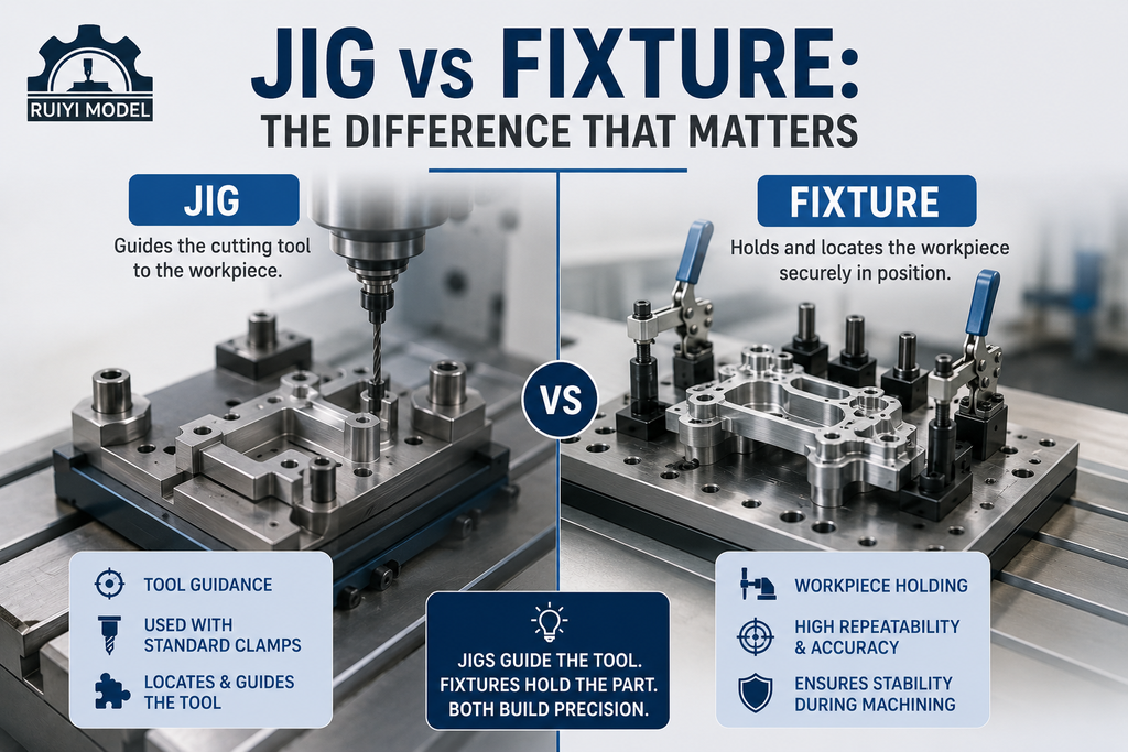
Jigs and fixtures are both workholding tools, but they serve different functions. A jig, such as a drill jig with hardened bushings, guides the cutting tool directly, ensuring holes land in the same place every time without measuring each part. A fixture holds and locates the workpiece but does not guide the tool. In modern CNC machining, most workholding built for mills and machining centers is technically a fixture, since the machine’s own coordinate system and programmed toolpath control where the tool goes. For a closer look at how this applies to production parts, see our earlier guide on what a fixture is and how the technology is developing.
The 3-2-1 Locating Principle
Any rigid part in space has six degrees of freedom, three translational and three rotational. The 3-2-1 principle is the standard method for controlling all six with the minimum number of contact points, which avoids the distortion and inconsistency that comes from over-constraining a part.
| Plane | Contact points | Degrees of freedom restricted |
| Primary plane | 3 points | Movement along one axis, rotation about the other two |
| Secondary plane | 2 points | Movement along one horizontal direction, rotation about the vertical axis |
| Tertiary plane | 1 point | The final remaining degree of freedom |
Matching locators to drawing datums
Fixture datums should match the datums called out on the part drawing wherever possible. Use machined reference surfaces rather than raw stock surfaces for locating, since machined surfaces are flat and predictable. Where the part already has a bore or slot, a locating pin sized to that feature is often more reliable than adding a new reference surface.
Clamping Strategy
Clamping force has to resist cutting forces without deforming the part, especially on thin-walled or delicate geometry. Toggle clamps suit manual, lower-volume work. Hydraulic and pneumatic clamps suit higher-volume production where fast, repeatable loading and unloading reduce non-cutting time. Clamps should always land on a rigid section of the part, never on a thin wall or unsupported span, and rest pads or support elements should be added under any area at risk of flexing. This is the same discipline behind our multi-part clamping fixture designs for batch production.
Fixture Body Material and Rigidity
Rigidity is the first rule of fixture design, since any movement under cutting load shows up directly as a poor surface finish or a scrapped part. Common fixture body materials include tool steel and cast iron for long production runs, and aluminum for lighter-duty or lower-volume tooling where weight and cost matter more than maximum stiffness. Reinforcing ribs and braces on weaker sections help without adding unnecessary mass.
Design Checklist for CNC Fixtures and Jigs
- Confirm the part’s critical tolerances and match fixture datums to the drawing datums.
- Apply the 3-2-1 principle and avoid adding locators beyond the six points needed.
- Place clamps on rigid sections only, away from thin walls or unsupported spans.
- Check tool approach and clearance so the cutter cannot collide with clamps or locators.
- Plan for chip evacuation so chips cannot build up under the part or against a locator.
- Design for fast, unambiguous loading so an operator cannot load the part incorrectly.
Frequently Asked Questions
What is the main difference between a jig and a fixture?
A jig guides the cutting tool to a precise position, while a fixture holds the workpiece securely and relies on the machine’s own coordinate system to control the tool path.
Why is the 3-2-1 principle used in fixture design?
It constrains all six degrees of freedom of a rigid part using the minimum number of contact points, which gives repeatable positioning without over-constraining or distorting the workpiece.
What happens if a fixture uses too many locating points?
Over-constraining adds unnecessary contact points that can force the part into a stressed or slightly different position each time it is loaded, which shows up as part-to-part variation.
Can the same fixture design be used across multiple part sizes?
Modular and reconfigurable fixtures can accommodate a family of similar parts, but a dedicated fixture is usually more rigid and repeatable for a single high-volume part.
Final Words
Good fixture and jig design is invisible when it works. It shows up as consistent parts, fast changeovers, and low scrap, not as a complicated tool. If your project needs a custom fixture designed alongside your production run, our online CNC machining services in China can build and validate the workholding as part of the same program.