
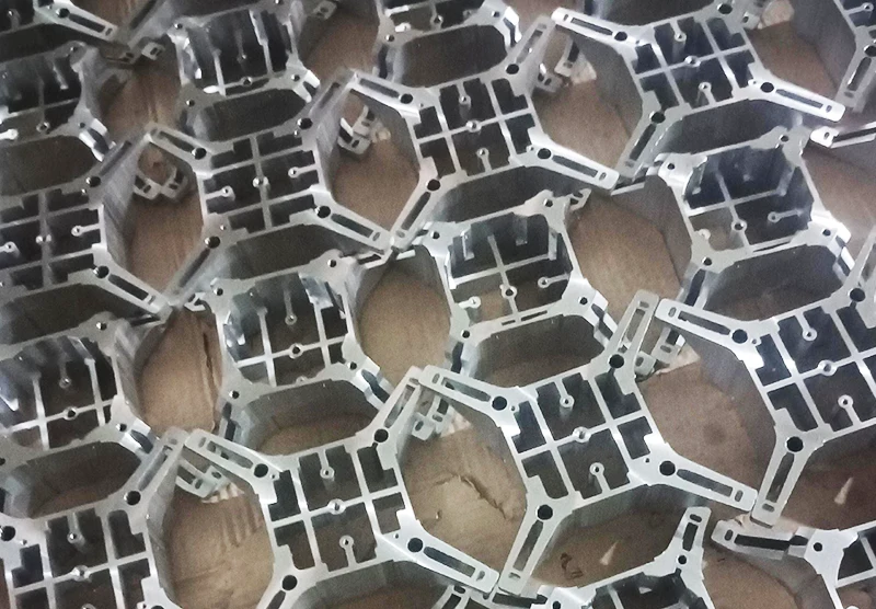
The quality and life of electromechanical products are largely affected by their surface quality.
Metal machining is one of the key processes that impact surface quality.
With the continuous progress of CNC technology, CNC machine tools have become widely used.
Additionally, computer-aided manufacturing (CAM) programming software is now widely employed, making the processing of complex parts more accurate and efficient.
However, the characteristics of different parts require different machining processes, and vibratory cutting “plays” a crucial role in surface quality problems.
Therefore, in the machining process of electromechanical products, a variety of factors need to be considered.
First, the choice of material directly affects the difficulty of processing and product performance.
Secondly, structural rigidity, clamping rigidity and machine rigidity will affect the stability and accuracy of the machining process.
Tool selection is also critical, as different tools are required for different machining tasks.
Additionally, the cooling system plays an important role in controlling the temperature during the machining process.
This helps reduce cracks and stress concentration, thereby extending the service life of the product.

Root fillet of the part appeared vibration knife and overcutting problems
In the field of manufacturing process, the surface quality of the bottom fillet is a critical assessment indicators.
However, in the side wall for the straight wall, the bottom for the free-form surface of the case, the manufacturing process, often encountered a series of problems.
In this case, the surface quality of the bottom fillet may not be satisfactory.
Experience has shown that when the sidewalls are straight and the bottom is free-form, a number of problems often occur with the bottom fillet.
First of all, wavy jagged marks are usually observed on the surface of the bottom fillet.
These marks are closely related to vibrations and instabilities during the machining process.
Secondly, some craters may appear.
These craters could be caused by material inhomogeneities encountered by the tool during machining or by improper setting of machining parameters.
In addition, there may be clear signs of tool vibration on the sidewalls, which may be caused by unbalanced cutting forces or high cutting speeds.
The existence of these problems not only affects the appearance of the bottom rounded corners, more seriously, may affect its functional performance.
Cause analysis:
In the program route problems, toolpath traces and vibration become critical.
Especially when dealing with free-form surfaces on the underside of the part, sidewall cutting becomes a critical factor.
Additionally, pit mapping and sudden changes in cutting force are also important considerations.
It was observed that tool vibration was often triggered when the tool path did not follow the root fillet, but rather moved closer to or away from the sidewall.
In this case, the increase in the root fillet allowance leads to an increase in cutting force, which further aggravates the vibration.
In addition, the radius of the tool fillet and the root fillet of the part are the same.
As a result, when the tool and the part come into contact simultaneously, the contact surface increases.
This increase in contact surface also leads to higher vibration, which may even cause tool vibration and overcutting.
Ultimately, this can result in the formation of small pits on the part.
Therefore, to solve this problem, we need to optimize the contact between the tool and the part.
This can be achieved by reducing the root fillet allowance, adjusting the tool fillet radius, and re-planning the program route.
These measures help reduce the vibration amplitude, ensuring the quality of the cutting process.
Solution:
First of all, we need to avoid frequent entry and exit of the tool in the round corner.
This not only increases the machining time but also leads to the deterioration of the surface quality of the workpiece.
Therefore, it is important to adopt a cutting strategy that follows the rounded corners.
This strategy not only improves machining efficiency, but also reduces vibration caused by sudden changes in cutting force.
As a result, it ensures the stability and accuracy of machining (as shown in Fig. 1).
For different types of bottom surfaces, different machining processes are required.
For the horizontal bottom surface, contour milling is the ideal choice.
This method allows the tool to follow the rounded corners, effectively avoiding unnecessary contact between the tool and the surface of the workpiece.
For the free-form bottom surface, a three-step machining process is required: first, finish milling of the sidewalls;
Then, finish milling of the bottom surface; and finally, finish milling of the rounded corners along the direction of the rounded corners, i.e., clearing the root operation.
In each step of machining, we should leave an appropriate bottom surface allowance and sidewall allowance.
This ensures that the bottom surface or sidewall will not be milled and helps avoid milling into the rounded corner.
These measures are crucial to ensuring machining quality and accuracy.

Root fillet of the horizontal bottom surface of the part occasionally appear a line of dents
The root fillet of the part refers to its sidewalls and the bottom of the intersection of the smooth transition, and the bottom surface is horizontal.
In cleaning the root fillet, occasionally appear dents, may stem from the machining process parameters of improper settings or tool wear and other factors.
These dents affect the appearance and quality of the part and therefore need to be recognized and resolved in a timely manner.
Improvement of machining process parameters and regular tool changes are effective measures to prevent dents.
In addition, regular checking of equipment condition and operating techniques is also critical to ensure the accuracy and quality of parts machining.
Therefore, for root fillet machining, besides technical means, operator’s experience and meticulousness are also crucial.
Strengthen the operator’s skills training and quality awareness education, help to reduce the frequency of dents, improve the overall quality level of parts processing.
Reason analysis:
CAM programming software has the function of automatically clearing the root when processing the model, however, this function has caused a series of problems.
Anomalies appeared in the toolpath design, and the Z-axis coordinates showed small fluctuations of about 2.1 microns.
To complicate matters, the machine’s axes had large backlash, especially in the Z-axis direction.
This causes the Z-axis to back off momentarily at the anomaly and then return immediately.
Although the small amount of Z-axis movement is smaller than the backlash, it is still enough to cause the Z-axis to crosstrain.
This ultimately results in the tool denting the workpiece surface.
While the automatic root clearing feature facilitates programming, it’s important to be aware of the challenges that may arise in practice.
Adjusting parameters or operations accordingly is essential to ensure the quality of the final machining.
Solutions:
First, adjust the tolerance values of the CAM programming software to optimize parameters and reduce the effects of Z-axis fluctuations.
Second, explore alternative programming methods, such as planar milling with NX software.
This approach helps reduce the need for the Z-axis, thereby minimizing the risk of fluctuations.
In addition to software adjustments, look at the machine itself, paying particular attention to Z-axis backlash.
If the gap is small, machine parameters can be adjusted to compensate and offset the negative impact on processing quality.
However, if the gap is too large, machine tool maintenance is necessary to ensure the stability and accuracy of the Z-axis.
Parts sidewall corner vibration knife and the problem of overcutting
The sidewall corner refers to the connection angle between the two sidewalls. When the sidewall is not vertical, it can lead to surface quality problems.
This issue is similar to the root fillet problems caused by tool vibration and overcutting.
However, if the sidewalls are perpendicular, the situation may be quite different and may require separate treatment.
In this case, additional steps or special solutions may be required.
Therefore, when dealing with this type of problem, it is important to consider the angle of the sidewall and the associated vibrating knife and overcutting problems.
Particularly when dealing with vertical sidewalls, care should be taken to ensure that the treatment is effective in resolving surface quality issues.
Cause analysis:
The tool does not match the radius of the corner and vibrates when cutting into the corner.
Vibration not only affects the quality of machining, but can also lead to tool damage or increased surface roughness of the machined part.
In addition, if the corner machining allowance is not controlled reasonably, excessive cutting force can occur.
This not only affects machining efficiency but may also damage the tool and machining equipment.
In addition, different materials and forms are required for different machining scenarios.
The choice of the appropriate tool material and edge form is also a key factor in improving cutting performance.
Furthermore, machining speed and high-frequency resonance of the tool are factors that affect stability.
Solution:
In the machining process, if the tool radius is smaller than the corner radius of the workpiece, or if the corner radius is increased, the problem of corner vibration can be effectively solved.
This results in a smoother machining process.
In addition, in order to reduce the machining allowance, first, roughing; then, finishing is the best practice.
When setting the depth of cut, reducing it to 0.2mm per cut is a good idea.
At the same time, the use of short tools or even customized machining tools can improve both the efficiency and quality of machining.
Additionally, enhancing the strength and rigidity of the tool is essential.
The use of high-strength, high-rigidity materials, such as cemented carbide, can help improve machining quality.
Additionally, choosing unequal helical flutes and considering vibration-resistant tools can further enhance both the quality and efficiency of machining.
When adjusting the machining speed, it is necessary to avoid the resonance frequency range of the tool.
The speed should be adjusted to effectively control vibration and resonance, ensuring the quality and safety of the machining process.
Problems with Vertical Sidewall Cuttering and Overcutting
When dealing with vertical sidewalls, engineers are often faced with a trade-off between two different approaches.
A common way is to use Z layered milling, that is, the thickness of each cut is relatively large.
While this method is effective in improving machining efficiency, the surface quality tends to be rougher.
Another strategy is to cut the entire sidewall directly with the side edges of the machining tool.
Although this method results in a higher quality surface, it requires more careful control of the machining process to avoid possible surface quality problems.
In selecting an appropriate machining strategy, engineers must weigh the situation on a case-by-case basis.
If machining efficiency is a priority, especially for mass production, Z-layer milling may be more appropriate.
However, if surface quality is critical or if precision machining is required, utilizing the side edges of the tool is preferable.
This approach, though, requires more careful process control.
Cause analysis:
In tool machining, especially when machining root fillets and bottom surfaces, tool vibration often occurs.
This vibration not only affects the surface quality of the machining but can also lead to cuts on the sidewall.
Setting the spindle speed parameter too high may be one of the main causes of tool vibration.
When the spindle speed is too high, the tool is prone to resonance.
This resonance intensifies the tool vibration, leading to instability in the cutting process. Ultimately, it affects the processing quality.
Insufficient rigidity of the tool system is also an important cause of vibration knife phenomenon.
The rigidity of the tool system, including the clamping length, tool material, tool edge form and so on.
If the rigidity of the tool system is not enough, it is easy to lead to excessive vibration of the tool in the machining process, thus affecting the quality of machining.
Solution:
A number of key factors need to be carefully considered when performing finishing operations, especially when dealing with sidewalls and bottom surfaces.
Firstly, it is important to allow for sufficient allowance and fillet, usually around 0.15mm.
The purpose of this step is to avoid vibration of the tool during machining.
This is especially important when cutting into the root fillet with a large margin, as it could cause bruising on the sidewall.
When machining the bottom surface, it is also necessary to leave allowances on the sidewalls and corners.
This helps prevent the tool from sticking to the sidewall of the part, which may otherwise cause unintended sidewall cuts.
In addition, after completing the finishing of the sidewalls and bottom surfaces, the corner rounding process is carried out separately.
This approach helps ensure the smoothness of the vertical sidewalls and meets the surface quality requirements of the parts.
In order to further improve the machining quality and efficiency, it is crucial to adjust the spindle speed.
By reducing the spindle speed, tool resonance can be effectively avoided.
This helps ensure the stability and accuracy of machining. In addition, improving the rigidity of the tool system is also very important.
With good rigidity of the tool system can effectively avoid vibration of the knife, thereby further improving processing quality and efficiency.
Parts of free-form surfaces appear bar-shaped pit overcutting problem
free-form surface machining, commonly used ball nose tool or round nose tool for reciprocating line cutting.
These two tools can effectively shape complex surfaces, but also accompanied by some quality problems.
Surface roughness is one of the most common, which can be caused by tool wear or inappropriate cutting parameters.
In addition, the appearance of spurs can be caused by tool vibration during machining or unstable cutting.
Irregular dents, which resemble brushed stripes, are often caused by vibration or uneven cutting during machining, as shown in Figure 2, left.
To solve these problems, it is necessary to carefully adjust the machining parameters to ensure smooth cutting.
Additionally, severely worn tools should be replaced in a timely manner.
In addition, the surface design and mold manufacturing before machining are also critical.
By optimizing the design and using high-precision molds, the occurrence of quality problems can be effectively reduced.
Cause analysis:
During the programming process, a large number of anomalies occurred due to the poor accuracy of the toolpaths.
Additionally, large gaps in the machine axes—especially in the Z-axis direction—affected the crosstalk of the machine.
In addition, the machine parameters are not reasonable and the tool is not sharp, etc. will have a certain negative impact on the machine crumbs extrusion.

Solution:
In order to improve machining accuracy and surface quality, a comprehensive approach is required.
It is necessary to consider factors such as programming tolerance accuracy level, tool path planning, and machine parameter adjustments.
Firstly, we increase the programming tolerance to ±0.003.
In addition, we adopt a 45° direction toolpath strategy. This approach effectively reduces small fluctuations in the toolpath and improves machining accuracy.
Next, we need to check the machine’s Z-axis backlash to make sure it is within normal limits.
If necessary, machine parameters can be compensated or repaired to ensure the stability and accuracy of machining precision.
During the machining process, it is crucial to use high-speed and high-precision machining instructions.
Conclusion
In summary, this paper presents a large number of practical proofs. During the CNC milling process, a series of surface quality problems in parts were identified.
These issues can be addressed by selecting different processing methods corresponding to specific parts.
Additionally, the appropriate use of various technological means can further improve the surface quality.
As a result, the overall quality of part processing is enhanced, which in turn boosts the core competitiveness of enterprises.

