
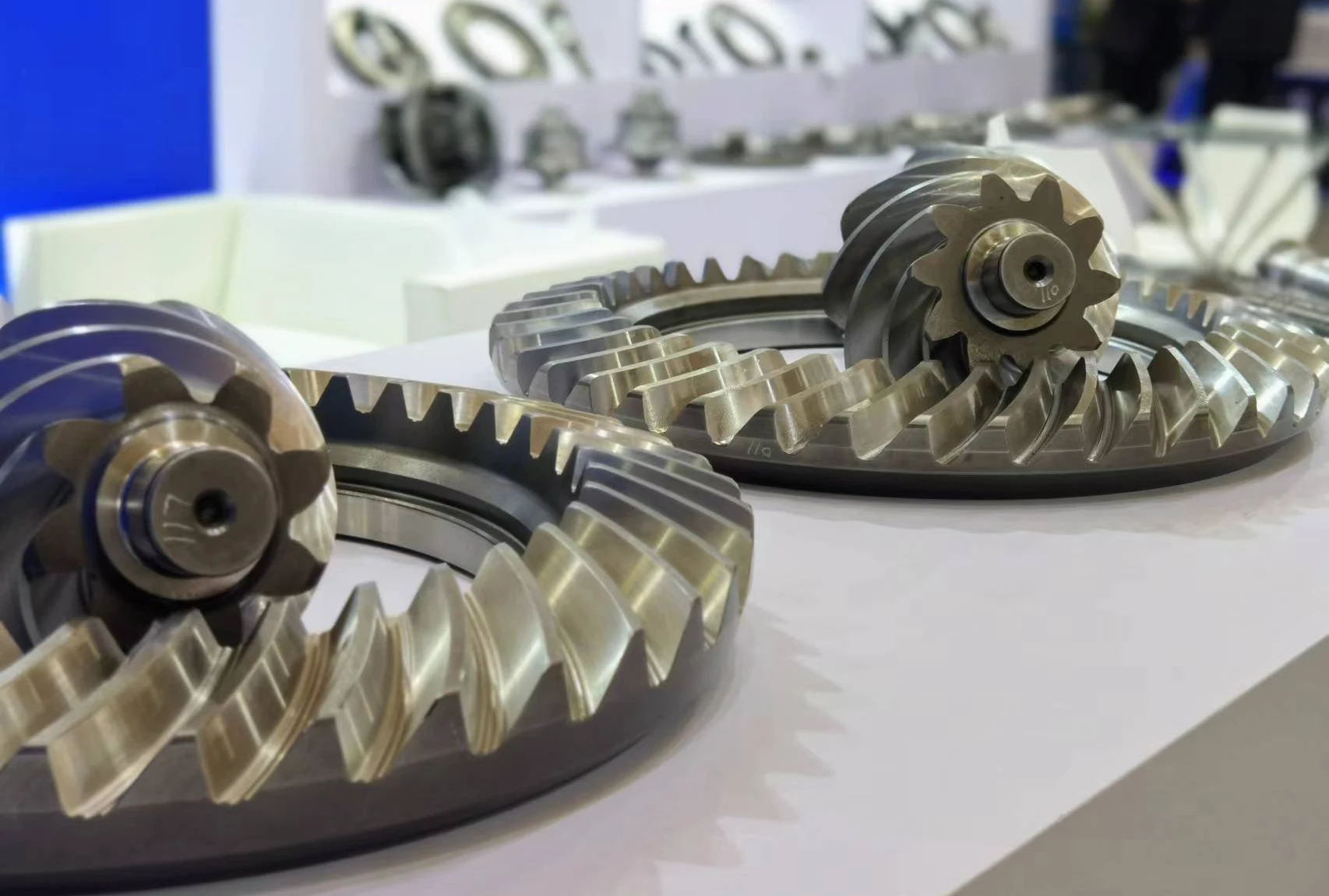
As a core component of transmission systems, drive worm gears are widely used in automobiles, construction machinery, and other fields.
Their threaded ends play a critical role in transmitting power and bearing loads.
However, during actual production, issues such as thread end breakage, jamming, and nut detachment frequently occur, severely compromising product quality and reliability.
Therefore, researching and improving the thread processing techniques for drive worm gears holds significant practical and engineering value.
Problem Analysis
Thread End Failure Phenomenon
A helical bevel gear produced by Jiangsu Feichuan Co., Ltd. for a medium-sized bridge exhibited thread end fracture during customer assembly, as shown in Figure 1.
This failure not only resulted in product returns but also severely damaged the company’s reputation.
To investigate the cause and resolve the issue, a detailed inspection and analysis of the failed component must be conducted.

Technical Requirements and Production Process Route
1. Technical Requirements
The following primary technical requirements apply to the threaded section of the drive worm gear:
(1) No microcrack defects shall be present in the thread, thread termination, R-radius corners, or similar areas.
These regions constitute critical stress concentration points in threaded connections, necessitating strict assurance of microcrack-free integrity.
The presence of microcracks accelerates thread wear and fracture, severely compromising the stability and service life of the gear system.
(2) The hardness of the threaded section shall be 288-596 HV0.3 or 30-55 HRC.
This hardness range ensures the thread possesses sufficient strength and wear resistance to withstand high torque and load. Hardness monitoring points are indicated in Figure 2.

(3) The thread hardness test surface, test location, and surface roughness are shown in Figure 3.

(4) Threads must be free of any visible defects such as impact damage, burrs, or broken teeth.
These defects can severely compromise thread fit and sealing performance, potentially leading to threaded connection failure.
2. Production Process Flow
Production process flow for threaded ends:
Machine-process C35 cylindrical surface → Pre-heat treatment threading → Apply anti-seepage agent to threaded section → Carburizing, quenching, tempering → Remove anti-seepage agent → Thread inspection → Finished product.
Failure Component Inspection
1. Hardness Testing
Hardness testing was conducted on the threaded end of the failure component, measuring from right to left at a distance of 5-8mm from the shaft neck.
Results are shown in Table 1. The table indicates that hardness in certain areas of the threaded end exceeds design specifications, revealing high hardness points.
Inspection of other thread sections also revealed isolated areas where hardness exceeded 560HV (50HRC).

2. Metallographic Examination
Metallographic examination revealed carbon enrichment in the threaded region (see Figure 4), while the core structure remained normal (see Figure 5).
This carbon enrichment caused an abnormal increase in hardness within the threaded area. Excessive hardness also increases material brittleness, thereby heightening the risk of fracture.
Compared to the threaded section, the core structure appears normal, indicating that the core material was unaffected by carburization and retained its original mechanical properties and microstructure.
The normal state of the core structure further highlights the abnormality of the carburization in the threaded section and its detrimental impact on the material’s overall performance.
")
")
3. Transition Zone Inspection
The hardness test results for the transition zone from the thread end to the shoulder are shown in Table 2.
As indicated in the table, the hardness of the transition zone ranges between 60-61 HRC, significantly higher than that of the threaded section, revealing a pronounced hardness gradient.
When subjected to external forces, the higher-hardness transition zone resists deformation, whereas the lower-hardness threaded section deforms more readily.
This deformation disparity generates substantial stress concentration near the transition zone.

4. Fracture Surface Examination
As shown in Figure 6, spectrum processing: No peaks omitted; Processing options: All analyzed elements (normalized); Number of repetitions = 5. The fracture surface examination results indicate a fatigue fracture surface with no inclusions.
This confirms that the failure at the threaded end resulted from fatigue damage caused by prolonged exposure to alternating loads.
The absence of inclusions in the fracture surface further supports the conclusion of fatigue fracture.

5. Visual Inspection
Visual inspection revealed intermittent flanging at the thread chamfer, some nicks on the threads, and wear marks on the nut’s internal threads.
Flanging alters the geometric shape of the thread end, potentially causing uneven interference or clearance during thread engagement, thereby compromising the tightness of the fit.
Additionally, the flange may increase assembly difficulty or even cause thread damage.
Impact damage compromises thread integrity, reduces effective contact area, and consequently diminishes load-bearing capacity and sealing performance.
Under dynamic loads, damaged areas may become stress concentration points, accelerating thread fatigue failure.
Wear reduces thread fit accuracy and load-bearing capacity, leading to loosening or leakage.
In extreme cases, wear may cause complete thread failure, triggering safety incidents. These issues collectively compromise thread fit integrity and service life.
Process Investigation
Through process investigation, the primary causes of thread end failure were identified as follows:
(1) Cracking of the anti-seepage agent resulted in high-hardness spots and carbon enrichment zones on the thread surface.
After cracking, the anti-seepage agent may form an uneven hardened layer on the thread surface, leading to a non-uniform hardness distribution.
These high-hardness spots and carbon enrichment zones alter the stress distribution on the thread, increasing the risk of stress concentration.
Under loading, these areas are more susceptible to plastic deformation, crack initiation, and propagation, ultimately causing thread failure.
(2) The transition zone exhibits higher hardness compared to the threaded section, readily forming stress concentration zones.
Hardness differences induce stress concentration at the interface between the transition zone and threaded area.
Under prolonged loading, stress concentration zones are prone to fatigue damage, leading to thread loosening or fracture.
(3) The threaded end features a flange, which complicates nut installation and removal, often resulting in misalignment and poor fit.
The flange alters the geometric shape of the threaded end, increasing assembly difficulty.
A misaligned nut fails to achieve a tight fit with the threads, compromising connection reliability and sealing integrity.
Under vibration or impact loads, the connection may loosen or even sustain thread damage.
Optimization Measures
Improving Thread End Appearance Quality
1. Impact Damage Issues
Customize different types of rubber protective sleeves based on the thread end’s outer diameter and structure.
These sleeves are typically made from high-strength, corrosion-resistant materials like nylon or polypropylene.
Determine the inner diameter of the sleeve according to the specific outer diameter of the thread end to ensure a snug fit that provides effective protection.
The shape and dimensions of the rubber protective sleeve are designed to accommodate the structural characteristics of the threaded end, including its length, pitch, and thread profile.
The rubber protective sleeve is applied immediately after the first threading process and remains in place until the customer’s production site.
A 100% inspection is conducted before shipment to ensure the threaded end is free from impact damage.
2. Flanging Issue
Machining chamfers at the thread ends prior to heat treatment exhibit flanging (as shown in Figure 7), and this flanging persists after heat treatment.

Improvements to Manufacturing Process: The 2×45° chamfer at the threaded end remains unchanged, with the addition of a 1xC31.5 step.
This design eliminates the end flange while the 1xC31.5 step provides guidance during nut insertion.
Improvements to the Inspection Process: Thread ring gauge inspection has been added. Passing the ring gauge inspection signifies acceptance for release.
Optimizing Performance Metrics for Threaded Sections, Transition Zones, and Spline Areas
1. Manufacturing Process Optimization
Following the original manufacturing process step “cleaning the anti-seepage agent coating,” the following three processes were sequentially added to enhance the mechanical properties of threaded sections:
(1) Induction Annealing: Employed multi-coil induction heating for 140 seconds, targeting the threaded section, transition zone, and spline area extending 3 cm above the transition zone.
(2) Stress-Relief Annealing: Subjected the induction-annealed drive worm gears to stress-relief annealing at 145°C with a 120-minute soak.
(3) Static Aging for 48 Hours.
2. Optimization of Inspection Processes
(1) Scheme Optimization
The original scheme only inspected one threaded section.
The optimized scheme: inspects three sections—the threaded section, the transition zone, and the spline section (3 cm above the transition zone).
As the primary load-bearing component of the connection, the strength and hardness of the threaded section are critical. The original plan already covered this key area.
The transition zone, connecting the thread and spline (or other structures), significantly impacts the connection’s reliability and durability through its hardness and strength.
Including it in the inspection scope helps identify potential stress concentrations and fatigue damage.
The spline area typically transmits torque and axial forces, where hardness and wear resistance are vital for connection stability and longevity.
The optimized plan’s inclusion of this area in inspections helps ensure the reliability and durability of the spline section.
The enhanced inspection scope now comprehensively covers critical connection points and potential risk zones, thereby improving overall connection reliability and durability.
(2) Hardness Optimization
The threaded section exhibits a moderate hardness range of 30-440 HV0.3 or 34-44 HRC, which satisfies load-bearing requirements while maintaining sufficient toughness to prevent brittle fracture.
The transition zone exhibits higher hardness at 400-575 HV0.3 or 42-54 HRC, which helps reduce stress concentration and fatigue damage, thereby enhancing the durability of the connection.
The spline section features the highest hardness at 544-635 HV0.3 or 52-57 HRC to meet the wear resistance and strength requirements when transmitting torque and axial forces.
Conclusion
This study addresses issues such as thread end fracture, jamming, and nut cap detachment by improving the manufacturing process for active worm gear threads.
Measures, including adding thread protection sleeves and guide steps, optimizing thread machining techniques, and establishing appropriate technical requirements have significantly enhanced thread end quality.
Experimental results demonstrate that the optimized threaded ends of the active worm gear exhibit significant improvements in appearance quality, hardness distribution, and stress state.
This enhances product reliability and service life. This research provides valuable reference and insights for improving manufacturing processes of similar products.

