
With the advancement of manufacturing technology, complex structural components are increasingly used in equipment manufacturing.
This trend drives simultaneous demands for higher machining precision and consistency.
These parts feature numerous curved surfaces, dense features, and constrained machining spaces, imposing greater challenges on toolpath control, tool orientation adjustment, and collision avoidance.
Traditional three-axis machining methods exhibit significant limitations in precision, efficiency, and accessibility.
Multi-axis CNC machining technology enables precise adjustment of tool movement direction and trajectory.
It achieves this through multi-degree-of-freedom coordinated control. This capability significantly enhances the machining performance for complex structural components.
This paper systematically reviews key multi-axis technologies based on the geometric characteristics and machining requirements of complex structures.
It analyzes their engineering application pathways through typical task studies, aiming to provide technical support for high-precision machining.
Complex Component Structures and Machining Requirements
Classification of Component Structural Features
Complex mechanical components typically exhibit intricate geometric characteristics.
These include multi-curvature spatial structures, nested inner and outer bodies, irregular holes and slots, and multi-faceted connecting elements.
Common external configurations include free-form surfaces like aircraft engine blades and compressor passages, or mold cavities featuring deep recesses and irregular internal cavities.
Certain structures also incorporate challenging machining zones.
These include ultra-thin walls, crank ribs, twisted surfaces, and inclined holes. Such features demand higher capabilities from machining equipment and path control systems.
Analysis of Machining Issues and Challenges
The machining of complex structural components presents numerous technical challenges. First, tool accessibility is particularly problematic.
Certain spatial surfaces or deep cavity structures are located in enclosed or obstructed positions, making conventional linear feed difficult to access and creating significant machining blind spots.
Second, dense local features combined with limited spatial clearance often lead to tool holder interference or cutting conflicts during path planning, compromising cutting continuity and part integrity.
Processing multi-faceted features necessitates frequent repositioning, which not only reduces efficiency but also facilitates cumulative measurement errors.
Thermal deformation during machining, thin-wall vibration, and burr retention can readily cause localized quality fluctuations or even structural damage.
Finally, the complex and variable surface topography demands exceptional path smoothness and residual machining control capabilities.
Minor deviations can readily produce quality defects such as step-offs and uneven surface textures.
Machinability Requirements
Given the aforementioned structural characteristics and machining challenges, complex structural components impose systematic performance demands on machining technology.
First, high-precision trajectory control is essential to maintain geometric accuracy along machining paths in non-planar regions with continuously varying curvature.
Second, machining equipment must support flexible multi-directional and multi-angle feed modes.
This capability enables multi-surface simultaneous machining and helps avoid accuracy loss caused by frequent clamping and manual flipping.
Simultaneously, path planning must exhibit high adaptability.
It should self-adjust to complex feature variations while ensuring smooth transitions between spatial surfaces and deep cavity structures. This guarantees continuous cutting.
To prevent tool impact and thermal concentration, the machining process requires excellent dynamic stability, enhancing overall surface quality consistency.
Additionally, comprehensive automatic recognition and auxiliary programming functions are essential.
They support efficient modeling and path generation for complex structures. This meets the demands of flexible manufacturing for small-batch, multi-variety production.
Principles and Characteristics of Multi-Axis Machining Technology
Classification of Multi-Axis System Structures
Multi-axis machining is also known as multi-coordinate simultaneous machining.
Most modern CNC machining equipment can achieve up to five-axis simultaneous control.
These machines vary widely in type, structural configuration, and control systems.
Multi-axis CNC machining equipment can be categorized into three-axis/four-axis, five-axis, and higher-degree-of-freedom systems based on the number of motion axes and structural combinations.
Among these, three-axis systems feature simple structures but exhibit significant limitations when machining free-form surfaces, inclined features, or spatial transition areas.
Four-axis systems incorporate an additional rotary axis, enabling multi-surface machining within a limited angular range.
Five-axis machining systems further add a second rotary axis, allowing the tool to achieve arbitrary angular orientation adjustments in space.
Common configurations include rotary table-type, swivel-head-type, and cradle-type five-axis centers, suited respectively for machining large workpieces, spatial curved surfaces, and mold cavity structures.
Key Elements of Multi-Axis Technology
The efficiency and precision of multi-axis machining rely on several core technological elements.
First is tool center point control (RTCP), which ensures the tool tip always follows the predetermined path regardless of tool orientation changes, unaffected by shank length or angular adjustments.
This effectively guarantees path accuracy and machining stability. Second is multi-axis simultaneous interpolation control technology.
By coordinating simultaneous interpolation across multiple coordinate axes, it achieves continuous cutting trajectories between free-form surfaces and polyhedral structures.
This enhances path smoothness and forming quality.
Third is dynamic posture adjustment, enabling real-time alignment of the tool axis with surface normals to minimize interference and abnormal loads.
Finally, interference detection and automatic avoidance functions utilize path simulation and machine tool spatial modeling to preemptively identify potential interference zones.
This dynamically adjusts the tool axis or entry point, ensuring safe tool operation.
Comparative Analysis of Multi-Axis Machining Advantages
Compared to traditional three-axis or four-axis methods, multi-axis CNC machining demonstrates systematic performance advantages in processing complex structural components.
These advantages are primarily reflected in tool accessibility, clamping methods, path continuity, machining quality, and interference handling (see Table 1).

Engineering Applications of Multi-Axis Machining Technology
Enhancing Spatial Surface Machining Accuracy
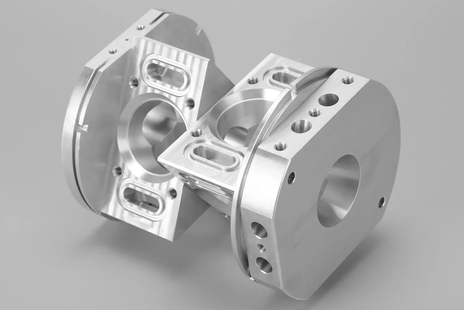
Spatial surface structures are prevalent in components such as aerospace blades, mold surfaces, and crankcases.
The key to their machining lies in ensuring the cutting path consistently aligns with the surface normal.
In multi-axis machining, the RTCP control function enables real-time linkage between tool orientation and path coordinates, guaranteeing precise tip movement along three-dimensional trajectories.
During practical implementation, operators should extract the normal vector information of the target surface within computer-aided manufacturing (CAM) software.
By integrating curvature variations to define the tool axis rotation range, the software automatically generates five-axis machining paths with integrated tool orientation control.
Adaptive matching between tool orientation and surface geometry is achieved by defining initial direction, curvature boundaries, and tool holder interference limits.
During machining, the RTCP control module is embedded within the CNC system to compute coordinate transformation matrices in real time.
It calculates these matrices based on tool tip position and tool axis angle changes, automatically correcting the execution trajectory.
This enables dynamic driving of the B-axis or C-axis based on trajectory changes without manual intervention.
It ensures consistency between tool orientation and surface normals, preventing path discontinuities or step defects caused by abrupt angular changes.
To guarantee machining accuracy, small ball-nose end mills should be selected, with step size and depth controlled to minimize surface disturbance.
In regions of abrupt curvature changes, the CAM path simulation module should predefine tool axis posture adjustment thresholds, limiting angular change rates to 3°–5°/mm.
When path-defined tool axis changes exceed this threshold, the CAM simulation and CNC execution systems automatically reduce angular velocity.
This prevents machine response lag caused by instantaneous posture changes, thereby safeguarding stability and surface quality consistency throughout complex surface machining processes.
Achieving Continuous Machining of Polyhedrons
Complex structures, such as deep cavity mechanical components, present challenges due to spatial constraints and high depth-to-diameter ratios, resulting in poor tool accessibility.
Conventional three-axis machining struggles to reach target areas or maintain optimal cutting postures.
Multi-axis machining enhances machining continuity and surface quality on deep cavity inner walls by dynamically adjusting B/C-axis orientations.
Starting from a reference plane, the toolpath automatically plans tool orientation through B/C-axis coordination.
This enables sequential machining of inclined surfaces, chamfered edges, and auxiliary holes within the cavity while avoiding interference boundaries.
Post-processing of the tool path is performed by the CAM path simulation module.
Users define the spatial orientation range (B-axis ±45°, C-axis ±180°) and combine it with geometric boundaries to generate orientation path interpolation (see Figure 1).

To achieve numerical solutions for attitude control, the control system employs tip position transformation formulas for trajectory correction, as shown in Equation (1):
Ptool=RB (θ)Rc (φ) Pbase+T (1)
In the equation, RB(θ) denotes the transformation matrix for the rotation of the B-axis about the Z-axis; Rc(φ) denotes the transformation matrix for the rotation of the C-axis about the Z-axis;
T represents the translation vector of the platform or tool center; Pbase denotes the tool coordinates in the original, unadjusted posture;
Ptool denotes the spatial position of the tool tip after posture linkage.
Tool axis angle changes are controlled within 10°/s to prevent instability during tool changes.
A long-shank ball-nose end mill is employed, combined with a machining strategy featuring a cutting depth less than 3 mm and a step size not exceeding 0.5 mm.
This approach enhances surface finish while reducing tool side pressure.
Avoiding Workpiece Interference Risks
Beyond adjusting path orientation, it is essential to address potential collisions between tool holders and workpiece structures, making interference avoidance strategies critical.
In multi-axis CNC machining, predefined avoidance strategies and path correction logic minimize the risk of machining failures resulting from interference.
Path interference detection begins by defining workpiece boundaries, tool geometry (shank length, diameter), and acceptable minimum clearance parameters within the CAD model.
The CAM simulation module analyzes all entry and transition segments during path generation based on the workpiece solid model and tool envelope contour, identifying potential interference zones.
It incorporates a normal offset mechanism into path planning for avoidance. The path adjustment principle is expressed by Formula (2):
-300x79.jpg "(2)")
In the formula, Pori denotes the original path point; n is the unit vector aligned with the surface normal direction of the interference zone;
λ represents the dynamically adjusted avoidance distance; Pnew signifies the new trajectory point after path correction.
To maintain machining continuity and path smoothness, the avoidance path does not employ discontinuous path breaks.
Instead, it dynamically adjusts the B/C-axis orientation to enable the tool to glide smoothly through space while rotating synchronously.
This approach avoids interference contours while ensuring the tool tip trajectory remains flush with the machined surface.
When the original path overlaps with the workpiece boundary, the path shifts a certain distance along the surface normal to generate a new path Pnew, accompanied by a fine adjustment in tool orientation.
This process is completed by CAM simulation prior to path generation.
During machining, the CNC execution module interpolates the B/C-axis rotation angles in real time, ensuring continuous, stable, and safe machining throughout the avoidance process (see Figure 2).

Adapting to Diverse Irregular Features and Working Conditions
After completing posture adjustment and collision avoidance, the machining path requires further dynamic reconstruction and parameter adaptation for complex irregular features.
The path construction module first performs boundary detection on areas such as inclined holes, asymmetrical protrusions, sharp angles, and intersecting angles.
Based on surface normal information, it invokes inclined linkage or helical entry strategies to maintain tool axis orientation aligned with the target surface normal, thereby reducing cutting impact.
Feature transitions employ inserted transition paths to prevent abrupt trajectory jumps; micro-step strategies are applied in confined spatial areas to enhance coverage accuracy.
The tool management module automatically selects and changes tools by integrating structural recognition with path instructions.
It prioritizes small-diameter, long-shank, or specialized tools to ensure machining integrity and surface quality within confined structures.
Throughout the process, highly coordinated posture control, path generation, and tool logic achieve high-precision, high-stability 5-axis machining of irregular features.
Typical structural types and common machining techniques with tool combinations (see Table 2) provide foundational support for subsequent path reconstruction.

The aforementioned machining technology not only enhances the adaptability and stability of path construction.
It also expands the intelligent response capabilities of multi-axis CNC equipment to diverse working conditions, providing technical support for the high-quality forming of complex structural components.
Conclusion
The machining challenges of complex structural mechanical components stem from their highly irregular geometries and stringent functional performance requirements.
Multi-axis CNC machining technology provides reliable support for achieving high-quality forming of complex structural parts.
It does so through attitude linkage control, continuous path interpolation, dynamic tool axis adjustment, and spatial collision avoidance strategies.
This paper analyzes the application of multi-axis machining in manufacturing processes by integrating key technologies such as RTCP, interpolation, and attitude cutting.
Practical experience demonstrates that the refinement and implementation of these technologies are crucial for achieving stable, safe, and efficient production of complex parts.
Future research should focus on advancing intelligent collaborative control of machining systems.
It should also enhance path optimization algorithms and develop adaptive fixture adjustment capabilities.
These efforts will drive the deeper integration and engineering application of multi-axis machining technology across broader manufacturing domains.

