Have you ever encountered those groove-type components in magnetic levitation vacuum pumps with extremely large lead and high thread counts?
Programming isn’t the hardest part of this job—the real challenge lies in the machining process and details.
One slight oversight, and you won’t meet the drawing’s precision requirements. Today, let’s discuss how to achieve accurate and stable machining for these two types of threads.
Category 1: Equal-Height Cylindrical Internal Threads
Both the thread crest and groove bottom lie on the cylindrical surface, appearing neat and orderly.
However, machining these produces significant vibration and is prone to tool wear.
If programmed conventionally with multiple cutting passes, the final pass often requires finishing, resulting in unstable dimensions.
Key Techniques
Layered Cutting + Complete Each Head Individually. Do not machine the same layer for all heads at once.
Instead, machine each head sequentially—from roughing to finishing—before moving on to the next.
This approach prevents inconsistencies caused by cumulative system errors and tool wear.
Category Two: Thread Peaks on Cylindrical Surfaces, Groove Bottoms on Conical Surfaces
This is more complicated because the thread groove bottom is tapered. When programming, you must not only calculate lead and number of starts but also account for taper changes.
Technical personnel’ve worked with a maximum lead of 280mm and 14 starts. If the program isn’t written correctly, tool path jumps occur, ruining the thread profile.
Programming Core
Taper slope calculation + macro variables controlling the X origin for each layer. Convert the taper into the X coordinate change per millimeter of Z movement (slope K).
Then, during each layer’s cutting, dynamically adjust the X coordinate based on the real-time Z position. Below is a practical program that technical personnel’ve used (9-start internal thread):
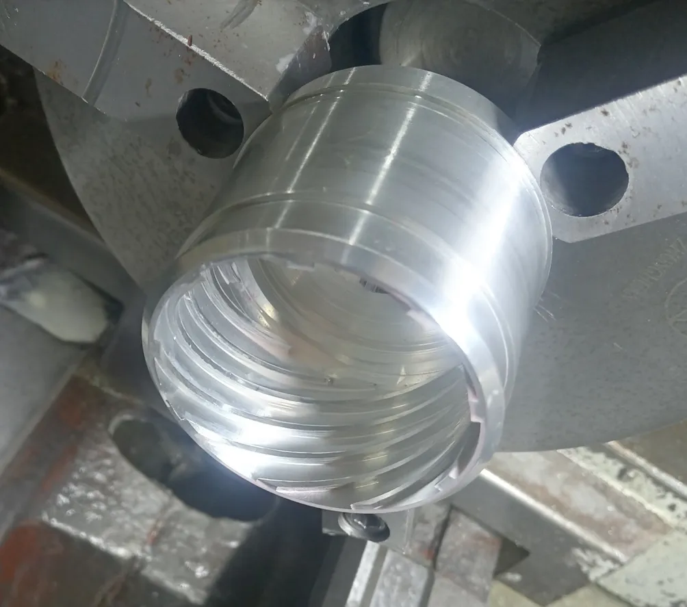
Technical personnel employed a macro program for easy debugging and reuse. Parameters were set based on the drawing: 88mm lead, 9 starts, aluminum material.
Below is the program for machining a large-lead multi-start internal thread:

Below is the processing video.
FAQ
What are high-profile cylindrical internal threads, and where are they used?
High-profile cylindrical internal threads feature prominently in precision components such as magnetic levitation vacuum pumps. They often have extremely large leads and multiple starts, requiring careful programming and machining to meet stringent dimensional and surface finish requirements.
What makes equal-height cylindrical internal threads challenging to machine?
Equal-height internal threads pose challenges due to vibration and rapid tool wear during cutting. Conventional multi-pass machining can lead to unstable final dimensions, especially on the finishing pass. Layered cutting and sequentially completing each thread head help maintain dimensional stability and reduce cumulative errors.
How do tapered-bottom internal threads complicate machining?
Tapered-bottom internal threads have grooves lying on a conical surface, making programming more complex. Machinists must calculate the taper slope, lead, and number of starts accurately. Failing to account for these factors can cause tool path jumps and distort the thread profile, particularly on large-lead, multi-start threads.
What programming strategies ensure precision in large-lead multi-start internal threads?
Precision is achieved by calculating the taper slope (slope K) and using macro variables to dynamically control the X coordinate for each Z-axis layer. This ensures that each cutting layer adjusts in real-time, preserving thread geometry and reducing errors caused by tool deflection or cumulative wear.
Why is sequential head machining important for internal threads?
Machining each thread head from roughing to finishing before moving to the next prevents inconsistencies caused by system errors and tool wear. This sequential approach ensures uniform thread dimensions across all starts and improves the reliability of high-precision components.
How can macro programming improve internal thread machining efficiency?
Macro programs allow technical personnel to automate repetitive calculations, dynamically adjust cutting coordinates, and simplify debugging. By setting parameters such as lead, number of starts, and material properties, macro programming ensures consistent, reproducible machining for complex high-lead, multi-start internal threads.


