
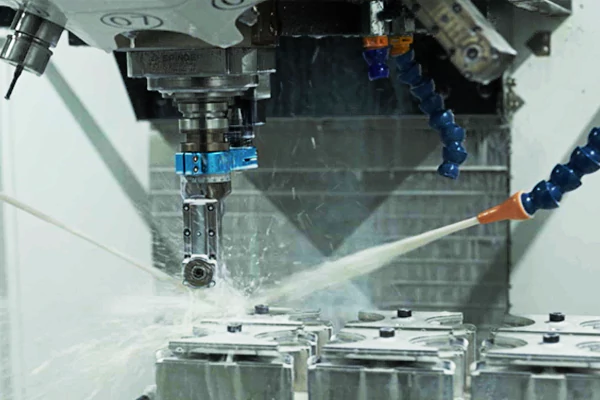
CNC machine tools are important and indispensable equipment in modern manufacturing. They rely on efficient and precise transmission systems and drive structures to realize complex machining tasks. This article will detail the characteristics of common CNC machine tool transmission systems, application examples, and technological advances to help readers better understand this field.

Advantages and examples of the five main transmission methods
1. belt drive
A belt drive is a common transmission method, especially in CNC machine tools, where it is widely used due to its simple structure and low manufacturing cost.
Advantages
Simple structure: the combination of belt and wheels makes the overall structure very simple, and easy to manufacture and maintain.
Low cost: Compared to other transmission methods, belt drives are less expensive to manufacture and are suitable for mass production.
Disadvantages
Slipping phenomenon: under overload conditions, the belt may slip, which can play a role in overload protection, but also limits its application in precise speed ratio occasions.
Speed limitation: Due to the problem of slipping, the belt drive has limitations in speed control.
Application Examples
In many CNC machine tools, the main motor drives the spindle via a belt, which is one of the most common applications for belt drives. Its low cost and ease of maintenance make it the preferred choice of many manufacturers.
2. Gear and rack drive
The combination of gear and rack is a classic transmission, they accomplish the conversion of motion by combining the rotary motion of the gear with the linear motion of the rack.
Advantages
High efficiency: Gear and rack transmissions have a high transmission efficiency and are suitable for position control requiring high precision.
High torque: They can transmit large torques and are suitable for driving heavy loads.
Application examples
Heavy-duty gantry feed axes are often driven using gear and rack drives. This configuration can effectively cope with heavy loads and high-intensity working environments, ensuring machining accuracy and efficiency.
3. Gear drives
Gear drives are the most common type of drive used in CNC machine tools. Their simple and compact structure and excellent performance make them important in a variety of applications.
Advantages
High torque transmission: gear transmission can effectively transmit high torque and is suitable for various machining scenarios.
Adaptable: able to adapt to variable speeds and variable loads.
Disadvantages
Speed limitation: when linear speeds are too high, the efficiency of gearing decreases, which can lead to wear.
Application Examples
Gear drives are commonly used in high-torque spindle drive mechanisms. This design provides strong power support while maintaining high efficiency.

Fig 1 Chain drive, Belt drive, Gear drive
4. Worm Gear Transmission
Worm gearing is another unique type of transmission that applications use when a large reduction ratio is required.
Advantages
Self-locking: Worm gears are self-locking and are suitable for positioning and holding heavy loads.
Compact: This type of transmission design is usually compact and suits applications where space is limited.
Application examples
The table rotation mechanism of horizontal milling machines widely uses worm gear transmission. This type of transmission can realize smooth rotation and precise positioning.
5. Threaded drive
Threaded drives use the meshing of a screw and a nut to transfer motion, primarily converting rotary motion into linear motion.
Advantages
High performance: Threaded drives can efficiently convert torque into thrust and are suitable for a wide range of applications.
High precision: Threaded drives excel in applications where precision is critical.
Application examples
Lead screw drives are widely used in many modern automobiles and CNC machine tools to achieve smooth linear motion.

Fig 2 Threaded drive
Table 1 Advantages and examples of the five main transmission methods

Drive systems for modern CNC machine tools
With the advancement of technology, new technologies continuously replace traditional transmission methods, and modern CNC machine tools strive for higher speed, higher precision, and higher rigidity.
1. Linear motor
Linear motor is an advanced transmission device that can directly convert electrical energy into linear motion.
Advantages
High speed: Linear motors are capable of very high accelerations and speeds, making them suitable for high-speed machining.
No backlash: Due to the absence of an intermediate changeover mechanism, linear motors have a very short response time, resulting in more precise movements.
Application examples
Some horizontal machining centers directly drive the rotary table with motors, greatly improving machining efficiency and precision.
2. Elastic coupling
Elastic couplings accommodate a wide range of misalignments and are commonly used in stepping and servo systems.
Advantages
Zero-backlash transmission: The one-piece design allows flexible couplings to transmit torque with zero backlash, improving system stability.
Good performance and price advantage: Flexible couplings perform well in many practical applications and are cost-effective.
3. Electric spindle
The emergence of the electric spindle marks a major innovation in the main drive system of high-speed CNC machine tools, which eliminates the traditional belt and gear drive.
Advantages
Zero transmission: The design of the electric spindle makes the length of the main transmission chain of the machine tool shorten to zero, which improves the efficiency of power transmission.
Improved machining accuracy: The direct drive reduces the energy loss in the transmission and improves machining accuracy.
4. Roller cam mechanism
The roller cam mechanism realizes intermittent motion and is characterized by high indexing accuracy and smooth operation.
Advantages
Self-locking and high accuracy: Self-locking can be realized during positioning, which ensures the stability and accuracy of machining.
Strong applicability: Suitable for use in conjunction with table exchange or tool changer mechanisms.
Table 2 Each transmission mode and its advantages and application examples

Characteristics of machine tool spindles
Due to the difference in transmission methods, there are obvious performance differences between the various types of spindles in use. Here we introduce and compare their characteristics in terms of space occupation, installation difficulty, limiting speed, noise, response speed, vibration, torque, cost, and machining characteristics.
1. Belt spindle characteristics
(1) Occupied space
Belt spindles require the installation of components such as tool-hitting cylinders, motors, mounting plates, timing pulleys, and timing belts on the spindle box. These components take up more space and the overall load is heavier.
(2) Installation Difficulty
Because the belt connection has flexible connection characteristics, the positional accuracy between the two axes, the machining accuracy of the accessories, and the assembly requirements are lower, but because of the large number of components, the installation process is more cumbersome. Attention needs to be paid to the correction of the pulley tooth jump, the accuracy of the parallelism of the spindle and motor axis, and the dynamic balance correction after the motor installation. In addition, the belt and pulley are in the inner cavity of the box, which increases the difficulty of installation and testing.
(3) Limiting speed
The limiting speed of the belt spindle is usually about 10,000 rpm. Due to the belt’s physical characteristics, it is difficult to ensure the controllability of vibration and noise at higher speeds, so increasing the speed is limited.
(4) Noise
Noise sources of the belt spindle include the rolling friction sound of the spindle and motor bearing, wind shear noise of the spindle, the current sound of the motor, cooling fan sound, and wind shear noise and tooth noise generated by the synchronous belt, the noise of the synchronous belt is more significant.
(5) Response speed
Spindle operation needs to be fed back from the motor to the synchronous belt and then to the spindle, the axis system is heavy rotational inertia, synchronous belt transmission friction,n, and deformation of large, large tooth gap, so the response speed is slow.
(6) Vibration
The motor and the spindle of the unevenness and the parallelism of the two axes, the belt drive reciprocating deformation, and tooth mesh affect its vibration, the higher the speed of the impact is more obvious, and the more difficult to reduce.
(7) Torque
The output speed or torque increase or decrease can be realized through the belt pulley. When the pulley ratio is 1:1, the output torque is slightly lower than that of a direct-connected spindle (friction loss).
(8) Cost
The cost of belt spindles is relatively low, mainly including spindle and accessory costs, maintenance costs, and labor costs. The flexible connection can effectively isolate the vibration of the motor and spindle, and cushion the spindle and motor when overloaded by the “crawling teeth” of the synchronous belt, thus protecting the spindle and reducing maintenance costs. However, due to the large number of parts and complex assembly, high labor costs, and more time-consuming diagnosis of fault points.
(9) Processing characteristics
The belt spindle has strong heavy cutting ability, but the angular positioning accuracy is low and the machining accuracy is relatively poor.
2. Characteristics of direct spindle
(1) Space Occupancy
The direct spindle system requires the installation of a motor, coupling, motor mount, and other components, occupying less space and load than the belt spindle. Due to the lower load, the response speed of the slide is faster compared to the belt spindle.
(2) Installation Difficulty
Due to the weaker flexible cushioning performance of the coupling, it requires a higher form tolerance between parts than the belt spindle, otherwise,e the additional load generated between different shafts may lead to increased vibration or even damage to the spindle and motor. When installing, it is necessary to ensure that the coaxially of the spindle, coupling, and motor axes reaches grade u and that the perpendicularity of the spindle axes to the motor mounting surface reaches grade u (the mounting surface usually needs to be shoveled and matched). However, the assembly process is relatively simple due to fewer parts.
(3) Maximum speed
The maximum speed of the commonly used direct coupled spindle usually reaches 24000 rpm. The higher the speed, the higher the coaxially of the spindle, coupling, and motor required. If the speed is to be increased under the qualified vibration conditions, it requires higher dynamic balancing precision, assembly precision, and precision of the coupling parts, which makes it difficult to increase the speed.
(4) Noise
The noise sources of the direct spindle include the rolling friction sound of the spindle and motor bearings, the wind shear noise of the spindle, the motor current sound, the cooling fan sound, anand nd shear noise of the coupling. Overall, the noise of the direct spindle is significantly lower than that of the belt spindle.
(5) Response speed
Spindle operation needs to go through the feedback from the motor to the coupling and then to the spindle, the shaft system is heavy rotational inertia is large, but the coupling flexibility is very weak, so the spindle operation response speed is faster than the belt spindle.
(6) Vibration
Direct spindle vibration is small, mainly due to the motor and spindle unevenness and spindle, coupling, and motoraxis coaxially. Compared to belt spindles, directly coupled spindles have lower vibration.
(7) Torque
The torque of the direct coupled spindle is provided by the motor and does not support the adjustment of output speed or output torque through the pulley or transmission system.
(8) Cost
The cost of a direct coupled spindle includes spindle and accessory costs, maintenance costs, and labor costs. The cost of the spindle and accessories is slightly higher than that of a belt spindle. Maintenance costs may be higher because the motor and spindle are often damaged at the same time. However, since there are fewer parts, the cost of assembly time is lower, and the point of failure is judged and repaired more efficiently.
(9) Processing characteristics
Directly coupled spindles have higher angular positioning accuracy because there is no free play between the motor and spindle and the coupling has less flexible deformation. There is no heat accumulation caused by the belt drive, and thermal stability is better. Due to the low vibration and high rotational speed, the machining accuracy of the direct coupling spindle is better than that of the belt spindle.
3. Characteristics of electric spindle
(1) Space Occupancy
The design of the electric spindle eliminates the need to install additional components such as motors and couplings, resulting in a smaller footprint and lower loads, making it particularly suitable for multi-axis linked machines. Due to the low load, the response speed of the slide is faster than that of a direct coupled spindle.
(2) Installation Difficulty
Since the motor is built into the motor of the motor spindle, installation is relatively simple and no additional external accessories are required. However, in order to meet the requirements of high rotational speed, the accuracy of the parts is very high, so the technical requirements for spindle suppliers are more stringent.
(3) Limit speed
Electrospindles are more conducive to the increase of rotational speed because they do not have the external force and impact of the intermediate transmission link. There are already 100,000rpm ball-type electric spindles in the market, and the speed of air-bearing electric spindles can even reach 400,000rpm.
(4) Noise
The noise of the electric spindle is low, mainly from the rolling friction sound of bearings, spindle wind cutting noise motor current sound, etc. Compared with the belt and direct spindle, its noise is the smallest.
(5) Response speed
Since the spindle has no intermediate transmission chain, the length of the transmission chain is zero, realizing the “zero transmission”. This makes the spindle system have a light moment of inertia and high acceleration, quasi-stopping accuracy and speed are also greatly improved.
(6) Vibration
The vibration of the spindle is low and is mainly affected by the machining accuracy of the internal parts, the quality of the moto,r, and the unevenness of the shaft system. Because there is only one shaft, the design of the shaft system facilitates the realization of lower vibration. At the same time, the high-speed operation keeps it away from the excitation frequency of the machine system, thus avoiding the resonance phenomenon.
(7) Torque
Since the motor is built-in and the installation space is limited, it is smaller than the motor fitted to a belt or direct spindle of the same specifications, resulting in slightly lower torque output and slightly reduced roughing capability.
(8) Cost
The electric spindle costs more than the belt and direct coupling spindles, but it eliminates the need for external motor coupling and other accessories, saving related costs. It also eliminates the cost of an external hydraulic station or booster cylinder, especially when installing cylinders. Due to the precision of the parts, maintenance costs are higher. However, the installation of the electric spindle is simpler, and built-in parts such as encoders and tool detection sensors reduce labor and time costs.
(9) Machining characteristics
The heavy cutting ability is not as good as the previous two due to the relatively low rigidity and torque. The small bearings and motors can result in low vibration. However, the cutting force is lower, less heat is generated, residual stress is reduced, and the finished product has a good finish while eliminating the need for the finishing process.
Table 3 Comparison of machine tool spindle characteristics

Future Trends
With the continuous progress of science and technology, the transmission system of CNC machine tools is developing towards higher speed, higher precision, and lower friction. In the future, intelligence and automation will become an important direction in the design of CNC machine tool transmission systems. The application of new materials, advanced control algorithms, and the improvement of precision manufacturing technology will inject new vitality into the transmission system of CNC machine tools.
Conclusion
The transmission system of CNC machine tools plays a vital role in manufacturing. Understanding the characteristics and application examples of different transmission methods will help us choose the right program in practice. With the continuous development of technology, the future transmission system will be more efficient, precise, and intelligent. I hope this article can provide you with references and help in the selection and application of CNC machine tools.

Solomon Yang is a manufacturing industry professional with extensive experience in electronic, mechanical, and industrial component manufacturing. Having held various positions in American and Taiwanese manufacturing companies, he has developed a comprehensive understanding of manufacturing processes, production management, quality control, and global supply chain operations.
With expertise in business development, sales operations, international trade, customer relationship management, and engineering project support, Solomon bridges technical knowledge with commercial strategy to deliver innovative and cost-effective manufacturing solutions. He is passionate about advanced manufacturing technologies, process improvement, and continuous professional growth, with a strong commitment to creating value for customers and partners worldwide.

