
Vacuum-Suction Fixtures are an effective solution for machining non-standard thin-walled aerospace components, which face challenges from complex geometries and tight dimensional requirements.
Clamping involves accurately positioning the workpiece and securing it without causing deformation, ensuring surface quality, dimensional accuracy, and positional precision.
Traditional fixtures—universal, specialized, electromagnetic, and modular—have limitations. Universal fixtures work for simple, small-batch parts, while specialized fixtures suit high-volume production but are costly.
Electromagnetic chucks provide quick clamping but only work with certain materials, and modular fixtures are flexible but expensive.
Many manufacturers still rely on universal and specialized fixtures, leading to lower efficiency and accuracy. Vacuum-suction fixtures use negative pressure to hold workpieces securely, avoiding localized stress and deformation.
They provide uniform pressure, precise positioning, rapid response, and reliable adhesion, making them ideal for delicate materials such as aluminum-magnesium and titanium alloys, as well as for optical components, aerospace blades, housings, and plastic parts.
Structural Analysis of Irregular Thin-Walled Components
Lightweight aerospace components with irregular thin-walled structures feature complex geometries including stiffeners, through-holes, and hollow cavities.
Figure 1 depicts a typical aerospace thin-walled part made of AL-6063-T4 (T4 condition: solution treatment + natural aging), with a tensile strength of 160–230 MPa.
This material exhibits favorable mechanical and physical properties with excellent machinability, making it widely adopted in aerospace applications.
The part demands high dimensional accuracy, positional accuracy, and surface finish quality, with the base surface requiring the strictest dimensional tolerance: thickness of 1+0.002–0.01 mm and flatness tolerance of 0.02 mm.
The side ribs have a wall thickness of 3 mm and a height of 24 mm, with a parallelism tolerance of 0.02 mm.
They exhibit poor rigidity and are prone to deformation, making machining challenging.
The bottom surface features a circular through-hole (milled).
Material and Machining Characteristics
The blank dimensions are 250 mm × 170 mm × 60 mm, with a regular rectangular prism shape. CAD analysis indicates the blank’s base area is approximately 4.3 × 104mm², with a mass of about 6.88 kg.
After machining, the part’s base area is approximately 2 × 104 mm², and its mass is about 0.32 kg.
The material removal rate reaches 95% of the total mass, indicating that the vast majority of the metal material is removed during processing.
Simulation data shows that the cutting processing time is approximately 6.5 hours.
Challenges in Workpiece Positioning and Auxiliary Operations
However, in actual processing, auxiliary times such as workpiece clamping and alignment are relatively long.
Workpiece positioning and alignment involve issues like high labor intensity and low repeat positioning accuracy, requiring verification through a first-piece trial cut.
Processing observations reveal that for a single part, cutting operations account for only 55% of total processing time, while auxiliary activities like clamping and alignment constitute approximately 45%.
Although additive manufacturing technology is maturing, its large-scale adoption in metal additive manufacturing remains limited due to challenges such as high raw material costs and relatively low efficiency.
Consequently, traditional metal cutting processes still dominate. Finally, the use of vacuum fixtures is proposed as an effective solution to the aforementioned issues.
These fixtures offer unrestricted clamping capabilities regardless of material or shape, enabling broad applicability.

Processing Technology Analysis
During rough machining, to enhance processing efficiency, it is recommended to use a flat-jaw vise for clamping while employing high-speed dynamic machining strategies.
A total machining allowance of 5mm is reserved for the entire model.
After completing the rough machining process, the workpiece must be disassembled to release internal residual stresses.
In the finishing stage, to ensure dimensional accuracy and surface quality, flat-jaw vise clamping alone can no longer meet the required machining precision.
A bolt-clamp method was adopted for workpiece clamping, employing a two-hole positioning configuration on one face.
Practical machining revealed that the bolt clamp required multiple position adjustments during processing, complicating the clamping procedure and introducing risks of interference between the tool holder and bolts.
Minor workpiece displacement during clamp adjustments adversely affected positional accuracy and surface finish.
Analysis of Tool Geometric Parameters
Cutting speed significantly affects cutting force; typically, increasing cutting speed reduces cutting force.
However, cutting speed is a critical factor influencing tool life.
For parts requiring extremely high dimensional accuracy, positional accuracy, and surface finish, diamond tools are the preferred choice.
These tools possess exceptional hardness, wear resistance, and cutting performance, making them particularly suitable for high-volume non-ferrous metal machining.
However, diamond tools carry a higher cost, necessitating judicious selection.
The number of cutting edges and helix angle parameters also significantly affect machining accuracy for thin-walled parts.
Data indicates that when machining AL-6063-T4 material, chips form in ribbon-like or fragmented shapes.
During rough machining, selecting tools with fewer cutting edges provides larger chip-removal grooves, facilitating efficient chip evacuation.
This prevents chip clogging that could compromise workpiece surface quality.
Fewer cutting teeth engaged in milling reduce cutting forces, minimizing workpiece deformation caused by internal stresses.
Selecting a milling cutter helix angle of 30°–40° also lowers cutting forces and noise levels, while a larger helix angle improves chip evacuation.
However, a larger helix angle increases the tool’s axial component force while reducing the radial component force, thereby minimizing thin-wall deformation caused by excessive radial forces.
Process analysis indicates that using an adhesive vacuum fixture for rough machining applies suction force to the workpiece’s base surface, resulting in minimal residual stress post-roughing.
The vacuum fixture incorporates a positioning mechanism enabling rapid alignment and clamping, effectively resolving the technical challenge of multiple disassemblies during machining of irregular thin-walled components.
When finishing both side walls, the 1:8 aspect ratio geometry induces significant cutting vibration, making dimensional accuracy difficult to achieve.
Employing a hot-melt adhesive filling process can effectively mitigate such vibration issues.
Vacuum Fixture Design
Given that aerospace components are typically single-piece, low-volume parts with specialized materials, an efficient vacuum fixture was designed to enhance productivity and ensure machining precision, addressing the challenge of clamping irregular thin-walled parts.
The design concept draws inspiration from the renowned “Magdeburg Hemispheres Experiment.”
Leveraging atmospheric pressure principles, a vacuum pump extracts air from the fixture’s interior to create a pressure differential, enabling secure adhesion to the workpiece.
The fixture body utilizes high-strength aluminum alloy for lightweight durability and corrosion resistance.
A rubber overlay enhances surface friction, ensuring stable workpiece retention.
Wear-resistant rubber seals maintain a consistent vacuum environment internally.
Multiple micro-perforations at the fixture base distribute suction force evenly, preventing localized stress concentration.
A vacuum pressure gauge monitors negative pressure in real time, while the vacuum pump features an automatic pressure regulation system to accommodate varying machining requirements.
The compact, user-friendly design enables rapid clamping of diverse thin-walled components with irregular shapes.
Adsorption Force Calculation
From a theoretical perspective, the magnitude of adsorption force Fadsorbs exhibits a certain correlation with contact area S and negative air pressure.
According to the formula Fadsorption= IPgauge pressure × l.S, the magnitude of the theoretical adsorption force can be calculated.
In this formula, Pvacuum represents the negative pressure differential, displayed on a vacuum gauge.
It denotes the difference between external atmospheric pressure and the negative pressure inside the vacuum fixture, i.e., Pvacuum = Patmosphere – Pabsolute (where Pabsolute is the absolute pressure inside the vacuum fixture and Patmosphere is the external atmospheric pressure).
Specifically, the negative pressure differential in practical applications correlates with the power rating of the vacuum pump.
When the vacuum gauge reads 60 kPa, the contact area of the blank’s bottom surface is approximately 4.3 × 10⁴ mm².
Using the formula Fadhesion = 6 × 10⁴ Pa × 0.43 m² = 2580 N. The blank’s adsorption force is thus approximately 2,580 N.
During finishing operations, with most allowances already machined, the contact area between the workpiece surface and fixture is only 2 × 10⁴ mm².
Calculations show the adsorption force during machining is 1,200 N. To verify the vacuum fixture’s reliability, further calculations of roughing and finishing cutting forces are required.
Cutting Force Calculation
To verify the reliability of the vacuum fixture’s holding force, theoretical cutting force calculations must be performed based on the physical properties of the workpiece material and the cutting tool parameters.
Data analysis is then conducted to validate whether the mechanical performance of the vacuum suction cup meets the machining requirements.
The cutting force calculation employs an empirical formula method, expressed mathematically as:
-1-300x62.jpg "(1)")
In the formula: CF is the cutting force coefficient, ap is the depth of cut, ae is the cutting width, fz is the feed per tooth, D is the tool diameter, Z is the number of teeth, and KF is the correction factor; x, y, z, and n are determined experimentally.
Consult the tool cutting manual to obtain cutting force parameters.
Calculate roughing, semi-finishing, and finishing cutting forces and machining times using empirical cutting force formulas. Specific parameters are shown in Table 1.
During roughing, high-speed dynamic machining is employed. Based on the tool cutting edge length, a large cutting depth ap and a smaller cutting width ae are selected.
Analysis indicates that rough machining efficiency has increased threefold compared to conventional methods.
During rough machining, the workpiece is a regular rectangle with vacuum suction force of 2580N ≥ 950N, meeting machining requirements.
For finish machining, a smaller cutting depth and feed rate are selected, with 1200N ≥ 205N satisfying machining requirements.

Working Principle of Vacuum Fixtures
The valve core is the critical component of a vacuum fixture, controlling the clamping and release of workpieces through linear reciprocating motion.
Figure 2(a) illustrates a simplified valve core structure, primarily composed of a piston, sealing ring, spring, and filter screen.
The seal ring is positioned at the end of the piston stroke. Under spring force, the piston fully contacts the seal ring to achieve sealing.
The filter screen captures fine chips to prevent air passage blockage.
Figure 2(b) illustrates a modular valve core structure, which operates similarly to the simple valve core but involves higher machining complexity.
This valve core incorporates two layers of filter mesh and three sealing rings, delivering superior sealing performance and chip filtration.
The valve core employs a threaded connection, enabling the piston to reciprocate within the core.
Advantages of the modular valve core structure include compact design, faster response speed, enhanced sealing effectiveness, and higher interchangeability.
◊ Operation of the Vacuum Fixture
The vacuum fixture operates as follows: when a workpiece is placed on the fixture’s upper surface, two scenarios arise.
In the first scenario, if the workpiece fully covers the fixture’s holes, the vacuum pump extracts air from the fixture’s interior cavity, creating negative pressure.
At this point, airflow can only pass through the gaps around the piston’s edges, preventing piston movement.
Negative pressure forms within the holes, thereby suction-fixing the workpiece. Multiple holes operating simultaneously further enhance holding force.
In the second scenario, when the workpiece does not cover the holes (e.g., when the workpiece is milled through), the piston automatically moves to the O-ring seal under negative pressure.
This seals the entire hole, preventing gas leakage and ensuring secure clamping.
After processing is complete, deactivating the vacuum pressure allows the spring to return the piston to its initial position.

The filter screen prevents chips and foreign objects from entering the clamping body cavity and compromising sealing integrity.
◊ Design Considerations and Key Components
The piston moves vertically within the bore cavity, where the clearance should neither be too large nor too small.
Excessive clearance may cause misalignment between the piston centerline and the bore centerline, while insufficient clearance reduces piston responsiveness.
Experimental data indicates that maintaining a clearance between 0.3 and 0.5 mm is optimal.
For machining the sealing groove, a T-slot cutter is selected.
Pay close attention to the machining precision of the T-slot, with both slot width and depth set at 2.4 mm; otherwise, sealing performance will be compromised.
The spring, filter screen, and sealing ring are all designed as standard components to facilitate subsequent maintenance and replacement.
It is particularly important to note that the spring and filter screen should be made of stainless steel to prevent rust from affecting the fixture’s sealing integrity.
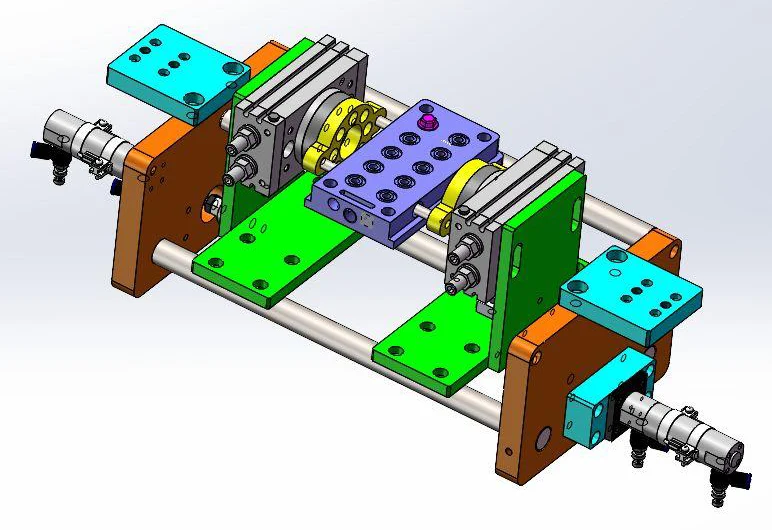
The three-dimensional model of the vacuum fixture is shown in Figure 3.
It can be subdivided into eight sections, with external dimensions of 450mm x 300mm x 60mm. Users may modify these dimensions as needed.
A key challenge addressed by the vacuum fixture is chip removal, particularly the fine aluminum chips generated during finishing operations.
Failure to promptly clear these chips can cause blockage of the valve core, compromising its sealing integrity.
To resolve this, a positive-pressure air vent was incorporated.
Upon completion of machining, applying positive pressure air clears both the fine chips and residual coolant.

◊ Dual-Chamber Design and Clamping Performance
To ensure sufficient clamping force, the fixture employs a dual-chamber design.
The positive-pressure air inlet connects to an air compressor. After machining, open the positive pressure valve to rapidly expel coolant from the fixture’s interior cavity using compressed air.
Before machining, ensure the positive pressure valve is closed. The vacuum gauge displays real-time vacuum pressure.
The vacuum suction port connects to a vacuum pump to evacuate air from the fixture’s interior.
A rubber gasket layer covers the fixture surface, serving two purposes: first, it effectively reduces vibration of thin-walled parts during machining; second, it prevents tool interference with the fixture’s working surface when milling through thin-walled parts.
The holding force of a vacuum fixture depends on three key factors: First, the power of the vacuum pump directly affects the holding force.
Second, the contact area between the fixture’s working surface and the workpiece surface—adding elastic rubber pads to the fixture’s working surface can enhance sealing effectiveness.
Finally, the distribution of suction points significantly influences the holding force.
Workpiece Positioning and Clamping
For rapid workpiece positioning, locating blocks or locating pins are typically employed as positioning elements.
Conventional process designs feature fixed locating blocks mounted to the fixture base via bolts, ensuring immovability throughout machining for secure reliability.
Floating locating pins utilize pneumatic control, where the pneumatic device displaces the pins axially during positioning to achieve rapid alignment.
After vacuum clamping is completed, the locating pins automatically retract to a safe position, preventing interference between the cutting tool and the pins during milling operations.
Compared to fixed locating blocks, floating locating pins offer higher operational efficiency but present greater design complexity.
Fixed Positioning Blocks
Positioning blocks are installed as shown in Figure 4. Aluminum alloy is selected for the blocks to prevent tool damage during machining.
Thin-walled parts require multiple clamping operations; positioning blocks enable rapid alignment, minimizing errors caused by clamping.
During finishing operations, appropriately adjust the fixture’s vacuum pressure.
After rough machining, the workpiece’s weight is reduced and its base becomes thinner.
Provided machining requirements are met, lower the vacuum pressure to prevent deformation caused by excessive suction.
During adjustment, perform gradual fine-tuning to maintain stable vacuum pressure and prevent workpiece displacement due to sudden pressure changes.

Floating Locating Pin
Before workpiece positioning, apply positive pressure. The piston moves the locating pin upward above the fixture contact surface under pneumatic force, enabling rapid workpiece positioning.
Once the workpiece is secured, negative pressure is activated, suctioning and fixing the workpiece in place.
Finally, the positive pressure is shut off, and the positioning pin retracts below the fixture contact surface under piston force.
This allows for milling of the workpiece’s outer contour without interference between the tool and the positioning pin.
The movement of the floating positioning pin is controlled by an electromagnetic solenoid valve for engagement and disengagement.
M-codes programmed into the CNC system control the vertical movement of the positioning pin, enabling automatic control and higher work efficiency.
Conclusion
Through an in-depth analysis of the structural characteristics of irregular thin-walled parts, a suction-type vacuum fixture was designed, proposing two valve core design structures for machining irregular thin-walled components.
The vacuum fixture design proves to be safe and reliable, effectively addressing the machining challenges of thin-walled components.
This demonstrates the practicality and effectiveness of the solution, while also providing favorable conditions for machining other types of thin-walled parts.
In practical applications, the fixture exhibits significant functional advantages.
Based on its operating principle, it can be designed as either a circular fixture or a multi-angle rotatable multi-functional fixture.
This design significantly enhances machining efficiency, optimizes product quality, and effectively reduces production costs.

Solomon Yang is a manufacturing industry professional with extensive experience in electronic, mechanical, and industrial component manufacturing. Having held various positions in American and Taiwanese manufacturing companies, he has developed a comprehensive understanding of manufacturing processes, production management, quality control, and global supply chain operations.
With expertise in business development, sales operations, international trade, customer relationship management, and engineering project support, Solomon bridges technical knowledge with commercial strategy to deliver innovative and cost-effective manufacturing solutions. He is passionate about advanced manufacturing technologies, process improvement, and continuous professional growth, with a strong commitment to creating value for customers and partners worldwide.

