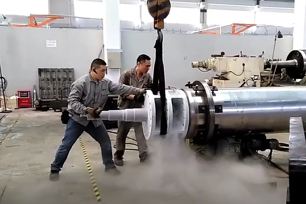
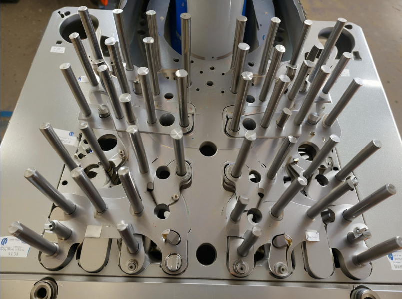
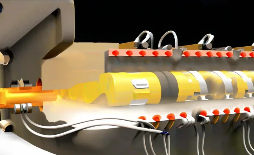
In the manufacturing industry, completing parts does not mean completing the task. We must assemble many parts to create a product that customers can use eventually.
In the assembly process of equipment or products, we commonly use hole shaft fit, which includes clearance fit, transition fit, and interference fit.
The interference fit often serves infrequent disassembly, high-strength connection, and high positioning accuracy, such as internal combustion engine piston pins, ship host shaft system whisk bolts, aircraft full motion winglets, etc.
With the upgrading of industrial equipment, the use of interference-fit parts is increasing.
The interference fit often uses dynamic or static pressure mounting, heating hole parts, and cooling shaft parts of three kinds of installation.
Dynamic or hydrostatic pressure installation will destroy the structure of the shaft hole and the theoretical amount of interference, reducing the assembly strength. High-demand occasions have limited use.
The principle of thermal expansion and contraction of the installation process from the interference fit into the gap fit is a standard method.
A nuclear power plant reactor pressure vessel and fuel assembly basket are made by different manufacturers; The gap between the two requires very high precision, and machinists need to create inlays to ensure accuracy.
To prevent the inlay block from moving during the 40 to 60 years of operation, which could cause a safety risk, we need to install a positioning pin with an interference amount of 0.001mm to 0.02mm to fix it.
Installation content and requirements
As shown in Figure 1, which shows the installation requirements schematic. The entire installation process consists of five steps:
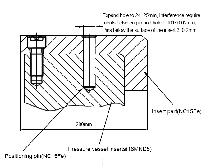
1) Finish machining the inserts according to the actual installation gap between the reactor pressure vessel and the fuel assembly basket;
2) Fixing the inserts with fasteners;
3) Machining the pin holes according to the design requirements;
4) Machining the interference locating pin according to the actual size of the pinhole;
5) Installation of locating pins. The following mainly discusses steps (4) and (5).
According to the design requirements, engineers can obtain a positioning pin made of NC15Fe with a diameter of 24mm to 25mm and an interference amount of 0.001mm to 0.02mm.
After we install the positioning pin, we should sink its upper surface into the surface of the embedded parts by 3mm ± 0.2mm.
Interference fit installation process selection
1. Hot assembly process analysis
The principle of hot assembly is to heat the hole parts (in this paper, it refers to the embedded parts), expect to increase the diameter of the pinhole through thermal expansion, the interference fit into a clearance fit, and the smooth installation of interference parts.
After analyzing, hot fitting is not applicable here for the following three reasons:
1) The pressure vessel integrates the hole part. The size of the pressure vessel is about Φ4700mmx13000mm, and the wall thickness is about 200mm, and it is challenging to realize the process of heating such a massive vessel.
2) Similar heat treatment will change the mechanical properties of the vessel.
3) As we analyze below, when we heat a part containing a hole, the hole’s diameter does not necessarily increase and may also reduce.
We can simplify hole parts to an inner diameter of the brother wall thickness of the D thin-walled tube model, which we can further simplify to a length of 2πR thickness of the D plate model, as shown in Figure 2.
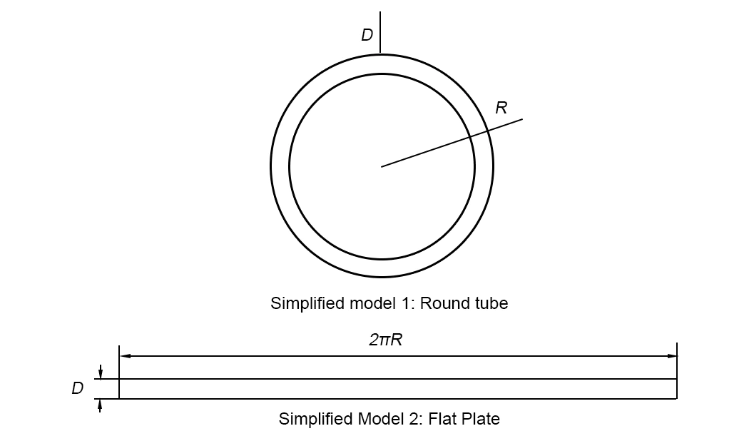
Temperature changes, the amount of change in the circumference of the circular tube is shown in equation (1):
![]()
In the formula:
ΔL – perimeter change before and after the temperature change, mm;
ΔR1 -radius before temperature change, mm;
π – circumference;
k – material linear expansion coefficient, mm/(mm-°C);
Δt – temperature change, °C.
According to equation (1), the change of radius of the circular tube after temperature change is shown in equation (2):

The change in wall thickness of the circular tube is shown in equation (3):

In the formula:
Δ D – amount of change in wall thickness before and after temperature change, mm;
D1 – wall thickness before temperature change, mm;
k – a material coefficient of linear expansion, mm/(mm-°C);
Δt – temperature change,℃.
According to the formula (2) and formula (3), the amount of change in the inner diameter of the hole is shown in equation (4):

According to the formula (4), we can analyze: the hole wall to the outer surface of the workpiece is thick enough, the temperature increases, may be less than zero, that is, the inner diameter decreases.
In summary, the hot loading process is not applicable here.
2. Cold mounting process analysis
The principle of cold assembly is to cool the shaft we need to install. As the temperature decreases, the shaft size decreases, and the shaft hole changes from an interference fit to a clearance fit.
The size of the positioning pin is about Φ24mmx110mm, which is small.
In addition to positioning in the power station’s operation, it does not bear other forces, and frozen performance changes will not affect the use of the feasible process.
Freezing medium commonly used dry ice (C02) and liquid nitrogen (n2). Dry ice at an atmospheric pressure temperature of -78.51 ° C, the temperature rises directly through sublimation, will not form a liquid.
Liquid nitrogen has a boiling point of -195.8°C and is fluid.
The two substances are chemically stable, odorless, non-toxic, non-conductive, and non-spontaneous combustion, suitable for cold installation.
However, the liquid nitrogen temperature is lower, and the pin parts shrinkage is greater.
It is in a liquid state, with a high heat transfer coefficient and shorter cooling time.
After sufficient cooling in liquid nitrogen, we can calculate the maximum cold shrinkage of the positioning pins using formula (5).
![]()
In the formula:
s – cold shrinkage, mm;
k – material linear expansion coefficient, take mm/(mm.°C).
D – diameter, take 24.5mm;
t – cooling temperature, take -195.8°C;
t0 – temperature before cooling, take the ambient temperature of 20° C.
After we calculate, the shrinkage is 0.0634mm. Through the experiment, we reduced the outer diameter of the 27.07mm positioning pin after freezing it with liquid nitrogen. We reduced the outer diameter to 27.00mm, and the shrinkage was 0.07mm.
The size minus the design requirements of the maximum interference is 0.018mm, 0.052mm. We can realize an ample clearance through the assembly.
Positioning pin frozen back to the temperature of the study
Position the pin in liquid nitrogen after completely frozen, removed in the air, and loaded into the positioning pin hole. Positioning the pin first and air heat transfer, then with the pinhole metal wall heat transfer, positioning the pin absorbs heat expansion to a certain extent and will not be able to fit into the pinhole.
1. Heat transfer between pin and air
Positioning pin material for NC15Fe has a thermal conductivity of 12.85W / (m – k); in the lack of convection, relatively static environment, the thermal conductivity of air is 0.023W / (m – k), thermal conductivity is low, heat transfer capacity depends on the air.
After we place the positioning pin in the air, the surface will frost, the heat transfer interface will continue to change, and the simple application of the formula can not accurately describe the heat transfer.
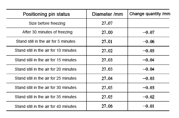
Therefore, through the test simulation of heat transfer on the impact installation, see Table 1.
We can derive from Table 1 that after placing the positioning pin in the air for 10 minutes, it returns to the temperature, and the diameter changes by only 0.02mm.
For the actual installation process, from the holding tank to load into the pinhole, skilled workers need about 15 s. The time and air heat transfer on the installation of the impact is minimal and can be ignored.
However, attention should be paid to the pin surface of the ice, appropriate control of air humidity, and loading speed.
2. positioning pin and pinhole wall heat transfer
Pressure vessel inlay material for 16mnD5, thermal conductivity of 80W / (m – k). Positioning pin material for nC15Fe, the thermal conductivity of 12.85W / (m – k).
We load the positioning pin in its frozen state into the pinhole due to about a 0.06mm gap. The gap between the pin and the hole does not make complete contact, reducing the heat transfer rate.
With the rapid expansion of the pin after heat absorption, the contact area increases rapidly, and the heat transfer and expansion rates increase exponentially.
nC15Fe thermal conductivity is about 560 times that of air, assuming that the installation of the whole process of the average contact area of 50%, to Table 1 in the data of the rough projection:
Pin in the hole 8s heat transfer is equivalent to 40min heat transfer in the air. 8s, the gap between the two is only 0.01mm, considering the hole and shaft processing may exist unevenly or have other defects. In 8s, the pin will not be able to load.
Through the test and installation experience, we load the pin into the hole, and after about 8 seconds, the pin becomes completely stuck, with hammering unable to push the positioning pin. Therefore, we should control the installation process within 6 seconds.
Conclusion
Based on the above arguments, it can be found that frozen shaft components have a broader scope of application than heated bore components in interference fit installation.
In the process of cold installation of shaft components, we should note the following aspects:
1) Hole machining and measurement.
Hole processing quality is the basis for smooth installation. Construction site conditions are limited, so the processing process should pay special attention to the amount of machining equipment and chip removal to ensure the quality of the hole.
At the same time, we should measure the full depth of the hole through the data to analyze the hole size, the uniformity of the full depth, and the work’s impact.
2) Cooling time should be sufficient
Shaft components placed in the cooling medium cooling time should be sufficient, depending on the calculation size or test data.
We should cool the clamping device simultaneously to avoid localized boiling of the liquid nitrogen during clamping and heating of the shaft component due to heat transfer after clamping.
3) Correction of installation position
Due to the shaft parts in the air heat transfer capacity is small, clamping out of the holding box, do not need to rush the shaft parts into the hole, you can properly correct the installation position for the next step in the installation to create good conditions.
4) Need to be completed in a very short time
The key process is to install the shaft parts into the hole. We need to complete the process in a very short period.
In this case, we need to complete the process within 6 seconds. If we exceed that time, the positioning pin will experience heat expansion and become stuck.
Therefore, it is necessary to invest resources in the simulation of personnel operations and the production of special tools to ensure the success rate of installation.
5) Pay attention to safety.
Pay attention to the liquid nitrogen insulation container insulation capacity, structural stability, and possible frostbite of the operator; operating in a confined space, the operator should pay attention to the nitrogen volatilization caused by the reduction of oxygen content and other safety hazards.

