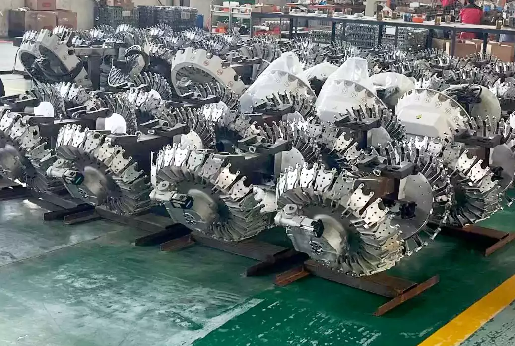
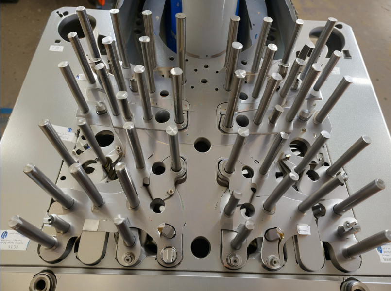
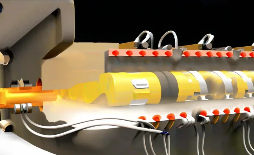
In CNC machining equipment, a carousel tool magazine (also known as a disc-type tool magazine) stores tools in a circular or disc-like structure.
Machining centers commonly use it to enable automatic tool changes, improving efficiency and reducing downtime.
The carousel rotates to position the required tool for the automatic tool changer (ATC), which then swaps the tool into the spindle.

Development History:
Early 1950s-1960s:
People first introduced CNC machines, but operators performed tool changes manually.
The need for faster production led to the development of early automatic tool changers (ATC).
1970s-1980s:
The first carousel tool magazines appeared, storing tools in a rotating disc structure.
Japanese and German manufacturers (e.g., Mazak, DMG, and MORI) began integrating ATCs into machining centers.
1990s-2000s:
Engineers developed higher tool capacity and faster tool-changing speeds.
Advanced sensors and servo motors improved tool selection and positioning accuracy.
2010s-Present:
Modern carousel tool magazines now feature AI-driven optimization, predictive maintenance, and integration with smart factories.
High-speed tool changers reduce downtime, and hybrid systems combine chain-type and carousel-type tool storage for maximum flexibility.
Famous Brands of Carousel Tool Magazines
Several well-known global brands manufacture high-quality carousel tool magazines:
Mazak (Japan) – Known for its advanced CNC machining centers with reliable tool-changing systems.
Makino (Japan) – Offers high-precision machining solutions with fast tool-changing mechanisms.
DMG MORI (Germany & Japan) – A leader in CNC technology with sophisticated tool magazine designs.
Haas Automation (USA) – Provides cost-effective CNC machines with durable tool magazines.
Fanuc (Japan) – Specializes in automation systems, including efficient tool changers for CNC machines.
Okuma (Japan) – Known for its high-speed and high-capacity tool magazines.
Doosan Machine Tools (South Korea) – Offers versatile machining centers with advanced tool magazine systems.
Hyundai WIA (South Korea) – Manufactures CNC machines with innovative carousel-style tool changers.
Advantages of Carousel Tool Magazines
Compact Design – This takes up less space than chain-type tool magazines, making it suitable for smaller CNC machines.
Fast Tool Selection – The circular rotation allows quick positioning of tools for efficient tool changes.
Simple Structure – Fewer moving parts reduce the risk of mechanical failure, ensuring reliability.
Cost-Effective – Carousel tool changers are generally more affordable and easier to maintain than more significant tool magazine types.
Improved Productivity – Reduces downtime by automating tool changes, increasing overall machining efficiency.
Development Trends
Higher Tool Capacity – Designers design modern carousel tool magazines to hold more tools while maintaining compactness.
AI and Smart Automation – Integrating AI-driven tool selection and predictive maintenance to optimize performance and prevent breakdowns.
Faster Tool Change Speeds – Advanced servo motors and robotic tool changers reduce tool change times to milliseconds.
Hybrid Systems – Some manufacturers combine carousel tool magazines with chain-type or matrix-type systems for greater flexibility.
Industry 4.0 Integration – Smart factories are adopting IoT-enabled tool magazines to communicate with CNC machines and manufacturing software for real-time monitoring.
Tool magazine structure
Here, we take the DK50 disc-type tool magazine produced by Taida Company as an example. The overall mechanical structure of the machine, as shown in Figure 2-1 (a), the physical figure, and Figure 2-1 (b) decomposition diagrams, shows that most of the current structure of the tool magazine is similar to this.
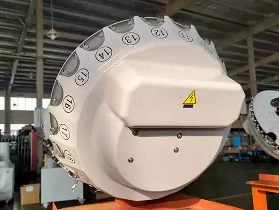
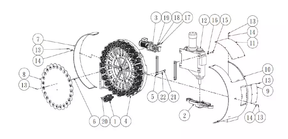
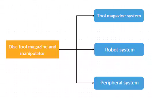
A disc-type tool magazine system generally consists of three parts: a tool magazine system, a robot system, and a peripheral system.
Figure 2-1 (d) shows the component systems, which are described below:
(1) Tool magazine system
The system mounts each of the 24 U-groove tool magazines on the disc, clamps the tool very securely, and holds the outer area in place by the support points of the disc. The operation of the tool pockets is driven by an electric motor driving the pockets.
The AC servo motor controls the rotation and traveling arrangement of the pockets and uses a coded plate to position them precisely.
For precise control, the tool change point is equipped with an optical checking power switch for the tool holder and a push cylinder that performs a push-in and return operation according to the up and down movement of the hydraulic cylinder, the task of the tool magazine is to complete the transfer of the tool between the magazine and the tool change point of the manipulator.
Two relays control the thrust cylinders for the extension and retraction movements.
As one of the key components of the tool magazine system, the toolset is shown in Figure 2-1(f).


(2) Robot system
The knife locking device follows the shaft pin to lock the knife sleeve securely in place to prevent the successful operation of the manipulator due to significant shocks, which would prevent the manipulator from changing knives. The knife locking sleeve is obtained using a separate relay, which controls the extension of the knife locking pin and its return to the changeover.
The heart of the tool-changing action is the manipulator. The manipulator uses arms, claws, taper pins, springs, moving pins, and clamping pins to perform the knife-gripping action.
The taper pin and the tool groove fit into each other. Precise positioning of the tool is accomplished, and the spring is matched to the movable pin to hold it against the tool groove mandrel, completing the tool hold.
The most critical component of the circular tool magazine and manipulator tool change system, the manipulator, is shown in Figure 2-1 (g), and the detailed parts drawing is attached as Exhibit 2:

(3) Peripheral system
Whether the whole tool change is completed is closely related to some peripheral equipment, including the power supply and automatic control system.
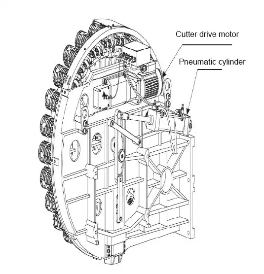
The power source includes the power supply and the cylinder, which must have a certain pressure and amount of gas for operation. The power and pneumatic system is the power and driving source of the tool magazine and manipulator. The motor provides power to drive the knife disc rotation.
The pressure of the disc manipulator to carry out the knife insertion and extraction action comes from the gas cylinder. As shown in Figure 2-1 (h):
Principle of Operation
Tool selection in the tool magazine
Each knife in a rotary tool magazine has a fixed position in the tool position, which is usually marked with Arabic numerals from 1 to 12, 18, 24, etc. The knife will return to its original position no matter how often it is replaced.
As long as an operator fixes a knife in a particular position, the knife will return to its original position no matter how many times the system replaces it.
The principle of determining the knife position is as follows: a start/stop button with no contact area is set in the tool magazine at the position where the knife is replaced, a grid is set at position 1, and each knife in the magazine needs to be returned to its original position before each run of the machine.
During operation, the digital control system marks the first time the compartment is within 0.3 mm of the start/stop button as position one.
The compartment has no contact area at this position. This system labels the knife positions in sequence accordingly.
The system keeps the labeling in effect during regular machine operating hours. The systems instantly fails the labeling when the machine switches off.
Tool changes are made using the counterclockwise nearest mark selection principle.
For example, if there are 24 tools in the magazine, the system requires the magazine to turn anti-clockwise to change to position 10 and clockwise to adjust to position 16 for the current tool number 12.
The disc-type tool magazine has limited space, and the stored 40# and 50# knives are within 24 and 20, respectively.
Principle of robotic tool change
The disc robot selects the tool based on random selection and the principle of proximity to the knife. Changing the knife updates all the knife sets and tool markers and records them in the database, achieving rapid and stable tool change. Specific steps for tool change:
(1) select the tool.
The machine tool operates under normal conditions. At the same time, the digital control system follows the T-code command.
The purpose is to move the tool from the initial storage location. The system moves the tool to the designated area for tool change.
This prepares the tool in advance for replacement during the next production step.
In the tool change process, the digital control system, under the M06 code command, is the tool magazine’s central axis to determine the parking position and the Z-axis to reach the tool replacement position.
(2) Robot grasps the knife.
The robotic arm grabs the knife. After the official start of the tool change, the cylinder drive activates the tool change sleeve in the tool magazine.
It rotates along the axis by a quarter turn. The tool axis in the tool magazine is parallel to the spindle axis.
The robot motor in the tool magazine starts working. The arc cam drives the robot to complete a 65° flip operation.
The robot’s claws simultaneously grasp the tool, change position, and put the tool in the spindle. This completes the final tool change process.
(3) Take out the tool.
The drive motor device of the robot in the tool magazine stops running immediately after the process of the robot tool change.
At the same time, the digital control system controls the gas-hydraulic equipment to dissipate heat from the spindle while the system releases the tool on the spindle.
The digital control system drives the robot to run the drive motor and adjust the robot’s drive mode for the plane cam drive during the tool release safety inspection. The plane cam will be pulled down the knife arm, ultimately removing the tool.
(4) Replace the tool.
After completing the above work of removing the tool, the robot of the tool magazine once again uses the curved cam drive to rotate for half a week to replace the tool in the tool magazine and the tool loaded on the spindle.
(5) Tool assembly.
After replacing the tool magazine in the spindle-loaded tool, the robot automatically switches back to the plane cam drive model, retracting the tool arm simultaneously while loading the tool to the tool magazine and the spindle.
Then, on the premise of switching off the robot’s drive motor, the digital control system drives the pneumatic-hydraulic device to make the spindle-loaded tool load firmly.
(6) Return to the robot.
In the fifth step, after completing the work, the digital control system drives to start the robot running motor, and the arc cam drives the robot slewing for half a week.
It drives the cylinder to make the tool change position tool and toolset on the turn of a quarter of a week. The robot completes the entire tool change process to return to its position.
Data exchange flow chart 2-2 (a) is as follows:
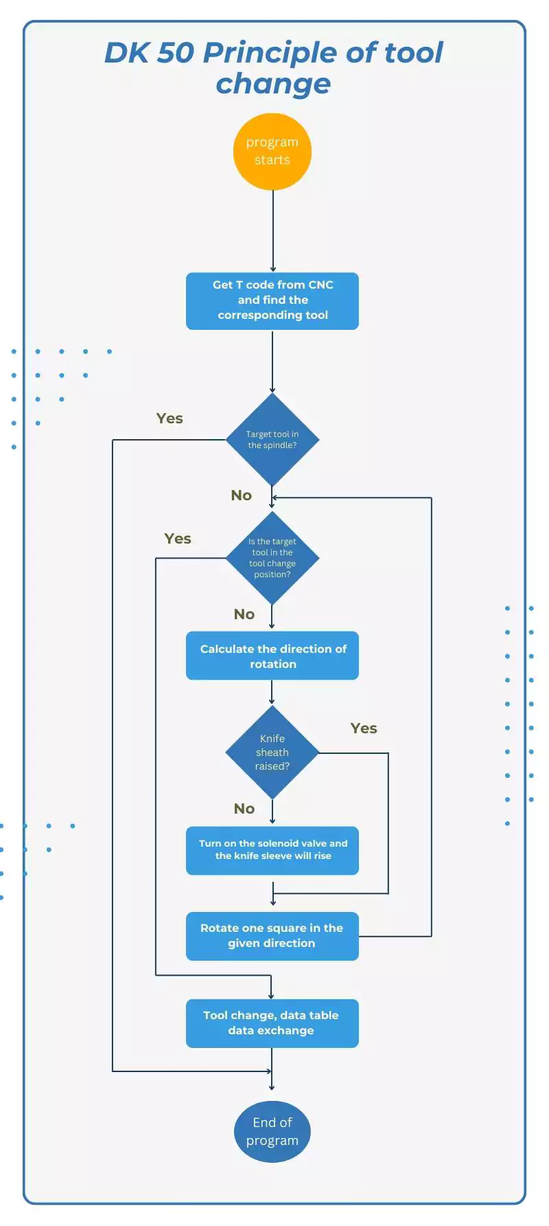
Tool Changer Operation Control System
Semi-Automatic Tool Changer Mode
In the semi-automatic tool change mode, the operator can use the combination control in the reliability test area to select the tool position according to his/her pre-setting.
The system changes the tool when the operator presses the start switch. At the end of a tool change, the operator presses the stop switch to pause the process, and presses the continue switch to proceed with the original tool change.
The semi-automatic tool changer model allows the operator to inspect and repair the tool changer system promptly, significantly reducing maintenance costs, such as regular contact between the tool changer and the toolset of drops of lubricant to the tool changer system for routine maintenance.
Figure 2-3 (a):

The actual meaning of setting manual mode depends on the convenience of maintaining the software of the automatic tool change system of the experimental target.
For example, adding grease between the tool sleeve and the tool magazine every week helps keep the collet free from damage.
During the weekly maintenance period, operators can promptly change the manual tool according to the fully automated method.
This allows the selection of tools that need maintenance.
The equipment can park the machine appropriately according to its stopping action.
This will be convenient for the operator.
Automatic tool change mode
In the semi-automatic tool change mode, the operator can use the system to select a tool number in the reliability test area randomly and then select another random tool number at the end of the current tool change, and so on, until the tool change process is complete.
The automatic tool change mode allows the operator to get more accurate and comprehensive test failure data, and the tool change system will stop working in case of failure or forced stop by the operator.
As shown in Figure 2-3(b):

Conclusion
The carousel tool magazine has played a crucial role in the automation and efficiency of CNC machining.
Evolving from manual tool changes in the 1950s to high-speed, AI-driven systems today, it has significantly reduced downtime and improved productivity.
Leading brands like Mazak, DMG MORI, Makino, Haas, and Fanuc have contributed to its advancement, integrating innovative technologies for precision and reliability.
As manufacturing embraces Industry 4.0, carousel tool magazines will further evolve with enhanced automation and predictive maintenance.
FAQ:
A carousel tool magazine, also known as a disc-type tool magazine, is a rotating circular structure used in CNC machining centers to store and quickly switch tools. It enables automatic tool changes via an automatic tool changer (ATC), reducing downtime and improving manufacturing efficiency.
The carousel rotates to position a selected tool at the pick-up point. An automatic tool changer (ATC) then retrieves the tool and installs it into the spindle. The process is controlled by a CNC system that executes tool changes with high precision and speed.
Key advantages include a compact design, fast tool selection, lower maintenance costs, simple structure with fewer moving parts, and increased productivity through faster and automated tool changes.
From manual tool changes in the 1950s to advanced AI-integrated systems today, carousel tool magazines have evolved to support higher tool capacity, faster tool change speeds, predictive maintenance, and Industry 4.0 integration.
Leading CNC machine manufacturers that use carousel tool magazines include Mazak, Makino, DMG MORI, Haas Automation, Fanuc, Okuma, Doosan Machine Tools, and Hyundai WIA. These brands offer reliable and high-speed tool-changing systems.
The DK50 disc-type tool magazine consists of three main systems:
Tool magazine system (holds and positions tools using servo motors),
Robot system (handles tool transfer using manipulators and arms),
Peripheral system (includes power supply, pneumatic cylinders, and control systems).
Tools are stored in numbered slots and return to fixed positions after use. The control system selects tools using proximity-based rotation (usually counterclockwise) and identifies tool positions using sensors and coded plates for precise positioning.
The tool change process involves six steps: tool selection, robot arm grabbing the tool, tool removal from spindle, new tool insertion, secure tool assembly, and return of the robot. These steps are fully automated and optimized for speed and accuracy.
Manual/semi-automatic mode allows operators to control tool changes for inspection and maintenance.
Automatic mode enables fully unattended tool changes with continuous operation, ideal for high-volume production.
Industry 4.0 integration allows carousel tool magazines to be IoT-enabled for real-time data exchange, predictive maintenance, and AI-driven optimization. These features help monitor performance, reduce failures, and increase overall equipment effectiveness (OEE).

