- misli-slots.com
- 4rabet
- pin up az
- pinap
- pinco casino
- mosbet
- pinup
- pin up casino
- pinup online
- 1 win az
- mosbet az
- 1win bet
- mosbet kz
- mostbet casino
- mostbet kz
- pin up
- mostbet az
- mosbet casino
- pin up az
- мостбет казино
- mostbet casino
- misli bahis
- mosbet
- pin up casino
- pinap
- snai casino
- mosbet az
- chicken road uz
- mostbet uz
- pin up
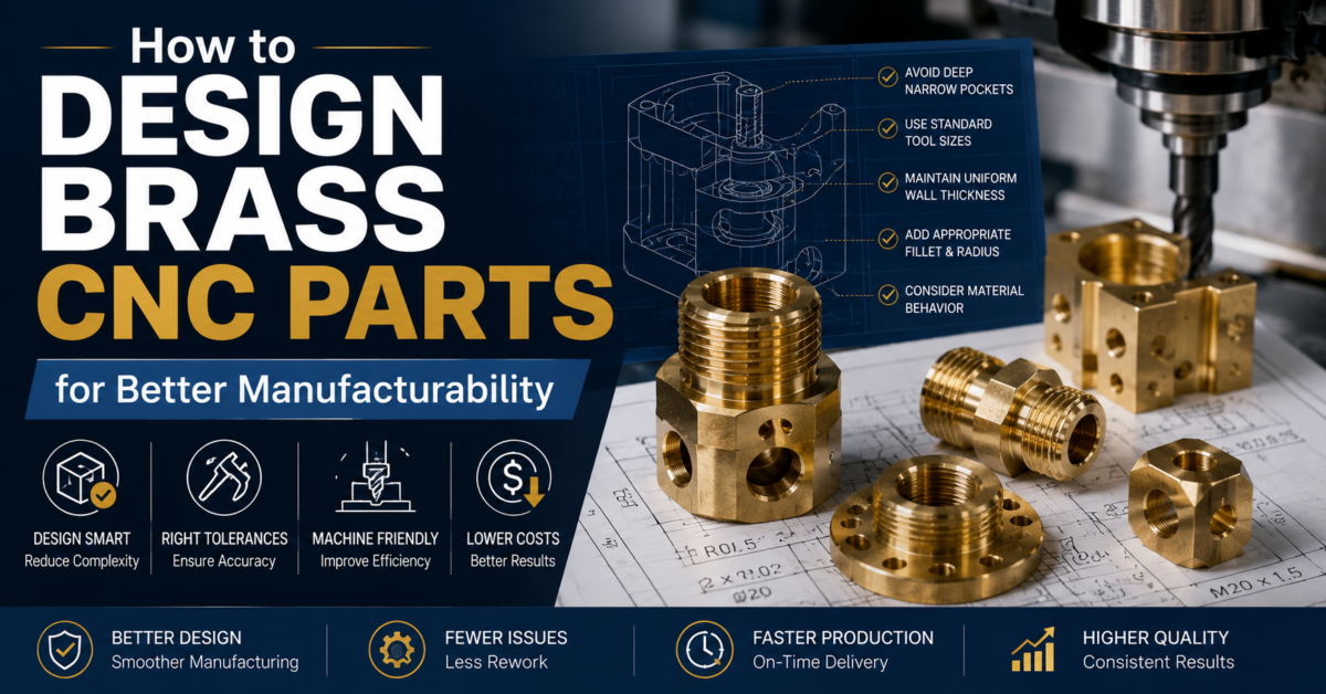
Brass is one of the most forgiving metals a designer can put in front of a CNC shop, but forgiving does not mean being immune to bad geometry. A part drawn without machining in mind still forces slower feeds, extra setups, and tighter-than-needed tolerances that add cost for no functional benefit. This guide walks through the design decisions that separate brass CNC parts drawing machines in one clean setup from one that bounces between the CAM programmer and the quoting desk three times, building on the alloy and process background in our custom brass CNC machining parts guide.
Key Takeaways
- Keep brass wall thickness at 0.8 mm or above unless a thinner section is functionally required and clearly flagged.
- Design rotational features on-axis where possible to avoid extra setups on turned parts.
- Reserve tight tolerances for features that actually control fit or function.
- Default to standard thread sizes and include relief grooves at thread ends.
- Match the finish to the part’s real function rather than specifying plating or polish by default.
Why Trust This Guide
These recommendations come from RuiYi’s engineering team reviewing brass drawings daily for CNC turning and milling production, not from a generic CAD design textbook. Every number below reflects what a real production floor can hold consistently, batch after batch.
Why DFM Matters More for Brass Than It Seems
Brass’s high machinability rating tempts designers into treating it as a material where geometry does not matter much. It matters plenty. A brass part with unnecessarily thin walls, non-standard threads, or tolerances copied from a tool steel drawing will still cost more to make than it should, even though the material itself cuts easily. The goal of designing for manufacturability, or DFM, is to get the part’s function at the lowest achievable cost and shortest lead time, not to make an already-easy material even easier.
Wall Thickness Guidelines
Brass and copper alloys tolerate thinner walls than steel because of their ductility and low cutting forces, but there are still practical limits. As a working rule:
- Target a minimum wall thickness of 0.8 mm to 1.0 mm for brass components in general production.
- Walls down to roughly 0.5 mm are achievable in a well-controlled shop, but expect slower feeds and a higher rejection risk.
- Keep the height-to-thickness ratio of any unsupported wall at or below about 4:1 to avoid chatter and deflection during cutting.
Thin sections vibrate under cutting load, and vibration shows up as chatter marks, dimensional drift, and in the worst case a cracked or bent feature during clamping. If a thin wall is functionally required, flag it clearly on the drawing so the shop can plan a slower finishing pass rather than discovering the problem mid-run.
The table below gives a quick reference for the numbers used most often when reviewing a brass drawing:
| Design Factor | Safe Default | Achievable With Care | Risk If Ignored |
| Wall thickness | 0.8 to 1.0 mm | ~0.5 mm | Chatter, distortion, cracked features |
| Unsupported wall ratio | 4:1 height-to-thickness or less | Higher with added support | Deflection, poor surface finish |
| General tolerance | ±0.05 to 0.13 mm | Tighter on flagged critical features only | Unneeded inspection cost |
| Pocket depth-to-width | 3:1 with standard tooling | Deeper with extended-reach tools | Slower cuts, tool flex |
Designing for Turning vs. Milling
Most brass CNC turned parts are rotationally symmetric: bushings, standoffs, connectors, and fittings. Designing with turning in mind means keeping features on-axis wherever possible, since off-axis holes require a secondary milling operation (live tooling or a separate setup) that adds cost. When a design does need off-axis features, grouping them so they can be machined in a single re-orientation reduces the number of setups and keeps concentricity tolerances easier to hold.
For prismatic brass parts machined on a mill, plan pocket depth-to-width ratios around 3:1 for standard tooling; deeper pockets need extended-reach tools that cut slower and flex more. Internal corner radii should match a standard end mill diameter wherever possible. A sharp 90-degree internal corner forces either a much smaller tool or an EDM operation, both of which add cost for a feature that rarely serves a functional purpose.
Did You Know? Free-cutting brass (UNS C360) is rated 100 on the machinability scale that every other CNC alloy is measured against, which is exactly why shops can run live-tool off-axis operations on brass at feed rates that would be aggressive on steel or stainless, without a second setup. Source: Copper Development Association.
Setting Tolerances Correctly
Brass can hold tight tolerances, but every tolerance tighter than the shop’s standard band adds inspection time and cost. A practical approach:
- Use a general tolerance of plus or minus 0.05 mm to 0.13 mm (roughly ISO 2768-m) for non-critical dimensions.
- Reserve tighter tolerances, and CMM inspection, for the two or three dimensions that actually control fit or function.
- If the part will be plated, specify whether each toleranced dimension applies before or after plating, since plating buildup on bores and threads is easy to miss until assembly fails.
Over-tolerancing is one of the most common and most expensive mistakes on brass drawings. A designer who marks every dimension plus or minus 0.02 mm out of habit is asking the shop to inspect and hold a precision level the part does not need, which shows up directly in the quote.
Threads, Undercuts, and Tool Access
Standard thread forms (metric coarse, UNC/UNF) use common taps, dies, and thread mills, which keeps tooling cost down. Custom or non-standard threads require dedicated tooling that has to be sourced or made before the job can even start. Wherever a thread ends against a shoulder, include a relief groove so the tool has somewhere to exit; without it, the last thread or two will be incomplete and inconsistent.
Undercuts such as O-ring grooves, T-slots, or dovetails need specialty cutters that typically add 30 to 50 percent to the machining cost of that feature compared with a standard pocket of the same depth. If an undercut is not functionally necessary, removing it is often the single cheapest change available on a brass part drawing.
Designing for the Right Finish
Brass’s natural as-machined finish already looks clean, which is one reason many brass parts ship without any secondary finishing at all. When a finish is specified, match it to the part’s actual function: hand polishing or buffing for visible, decorative components; bead blasting for a uniform matte texture on functional parts; plating only when the application specifically calls for a different surface color, added wear resistance, or solderability that raw brass cannot provide on its own. Our surface treatment services cover each of these finishing options in-house.
Common Mistakes in Brass Part Design
- Copying tolerances from a steel part without reconsidering what the brass component actually needs to hold.
- Specifying a custom thread when a standard size would do the job just as well.
- Leaving sharp internal corners on pocketed features instead of matching a standard tool radius.
- Ignoring plating buildup on critical bores and threads, leading to assembly problems after finishing.
- Designing thin walls without flagging them, leaving the shop to discover the risk mid-production instead of during quoting.
Reviewing hundreds of brass drawings over the years, the same handful of small edits keep coming up as the difference between a smooth production run and a reworked one: adding a radius, relaxing an unnecessary tolerance, or reorienting a feature so it machines in a single setup. None of these changes affect part function; all of them affect cost. These brass-specific issues sit alongside the broader patterns in our guide to 15 CNC part design mistakes that increase manufacturing costs, which applies across materials. Once your design is locked, our guide on selecting a CNC machining brass parts supplier covers what to look for before committing to a production partner.
Get a DFM Review of Your Design
RuiYi’s engineering team reviews every brass drawing for manufacturability as part of quoting through our CNC machining cost calculator. Turned brass components run through our CNC turning services line, and milled brass parts through our CNC milling services.
Frequently Asked Questions
What is the minimum wall thickness for brass CNC parts?
A safe general target is 0.8 mm to 1.0 mm, with thinner sections down to about 0.5 mm possible under controlled shop conditions.
Should I use standard or custom threads on brass parts?
Standard threads should always be the default. Custom threads require dedicated tooling and add lead time and cost without a functional benefit in most cases.
How much should I tolerance a brass drawing?
Use a general tolerance band around plus or minus 0.05 to 0.13 mm for most dimensions, and reserve tighter tolerances for the few features that control fit or function.
Does plating affect brass part tolerances?
Yes. Plating adds thickness that can affect bores, threads, and other tight features, so tolerances should specify whether they apply before or after plating.
Can brass CNC turned parts have off-axis holes?
Yes, most shops can add off-axis holes to turned brass parts using live tooling, though grouping these features to minimize re-orientations keeps cost down.
Final Words
Good brass part design is mostly a matter of not fighting the material. Keep walls reasonable, threads standard, tolerances honest, and finishes tied to actual function, and a brass drawing will move through quoting and production without the back-and-forth that eats into both budget and schedule. The shops that machine brass well will tell you the same thing: the best parts are usually the simplest ones that still do the job.