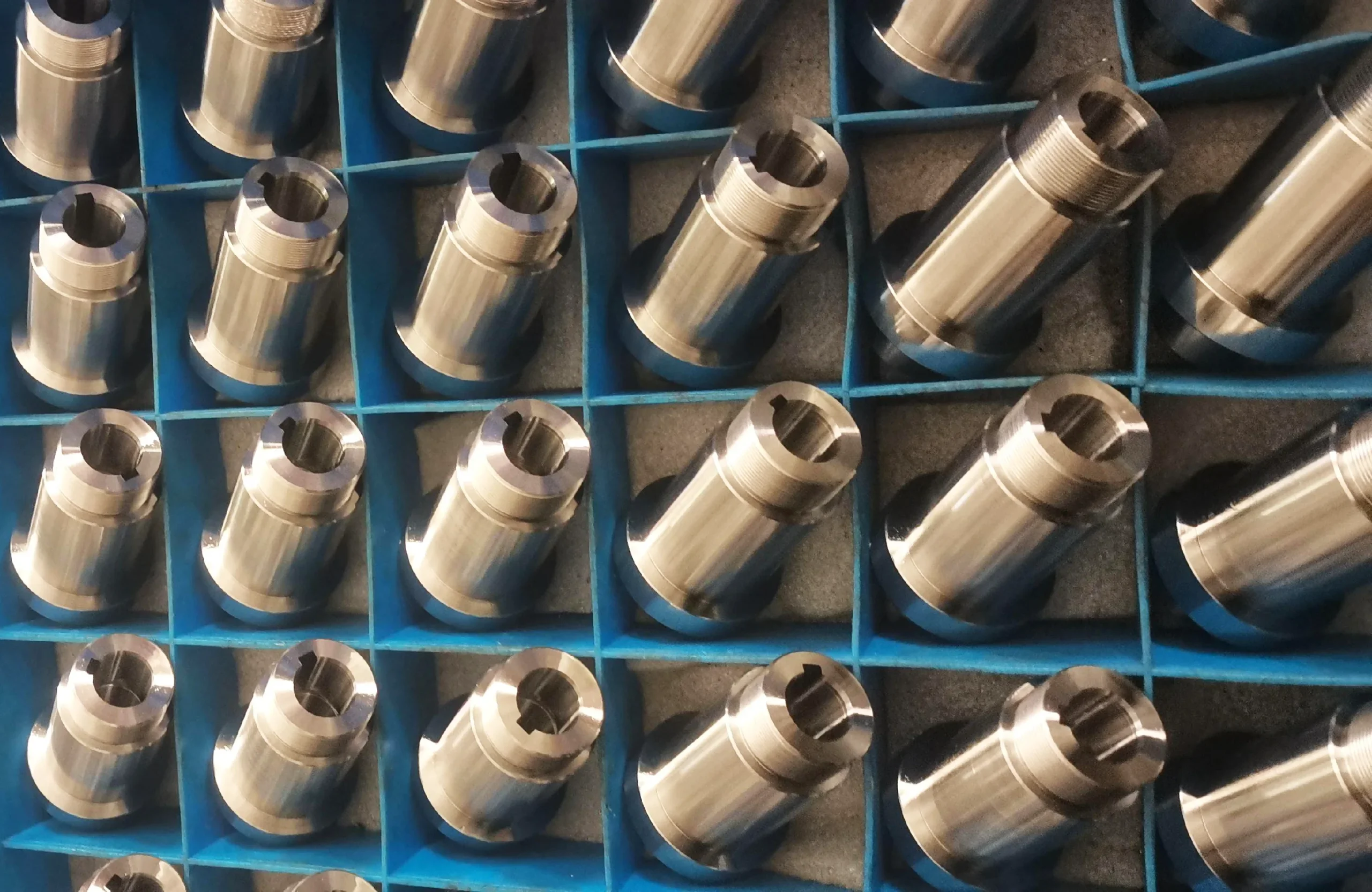
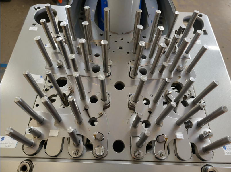
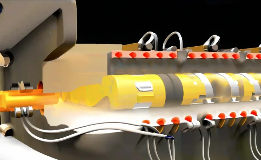
Buffer positioner is an important part of plunger gas lift drainage gas extraction device, the main working principle:
When the plunger hits the cushion positioner downward, the cushion positioner begins to move downward due to the impact.
On the one hand, the cushion positioner converts the kinetic energy of the plunger into the potential energy of the spring.
This conversion happens through the compression of the cushion spring. It significantly reduces the instantaneous impact load.
As a result, the kinetic energy of both the plunger and the cushion positioner is alleviated. This effectively protects the integrity of both the plunger and the cushion positioner.
On the other hand, the plunger is positioned in the groove between the oil pipe and the oil pipe clamp to realize the function of plunger falling.
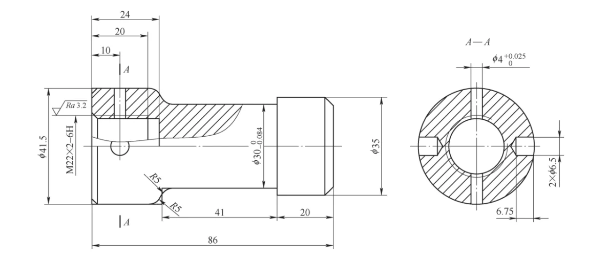
The salvage head shown in Figure 1 is the top part of the cushion positioner, made of 3Cr13 stainless steel, with a hardness of 250-280HBW after tempering.
This part is the direct contact and impact of the plunger when it falls to the ground, and it is also the key part of the late salvage buffer positioner.
Material Requirements and Thread Quality for the Salvage Head
The salvage head blind hole thread M22×2-6H is coupled with the core rod for compression of the buffer spring.
A surface roughness value of Ra ≤ 3.2 μm is required. The quality and reliability of this thread are important factors. They affect the functional integrity and strength of the buffer positioner.
This paper takes the buffer positioner salvage head (hereinafter referred to as “salvage head”) M22×2-6H blind hole thread as the object of study.
It carries out research on the problems arising from the actual processing of this thread. The paper also puts forward corresponding countermeasures.
These countermeasures are based on the author’s accumulated working experience. The aim is to provide these insights for the reference of counterparts.
Problems
In the mass production process of salvage head, since M22×2-6H blind hole thread belongs to fine pitch thread, the method of turning is economical and efficient.
However, limited by the structure of the blind hole thread and the cutting performance of the material, the thread has the following problems in the actual turning.
(1) Challenges in Chip Removal for Blind Hole Thread Processing
The chip removal performance is poor. Compared with the processing of external threads and through-hole threads, blind hole thread processing presents additional challenges.
This is due to the narrow internal space in the blind hole. As a result, chip formation is easily retained within the hole.
The residual chips retained in the hole can scratch and strain the processed surface. This, in turn, affects the processing quality of the thread.
The use of chip removal hooks to hook out the chips in the hole there is a safety hazard, the use of ordinary high-pressure air gun blowing chip effect is not ideal.
(2) Impact of High Material Strength on Tool Life
High material strength, high cutting temperature, resulting in low tool life, frequent downtime for tool change.
This is due to:
① 3Cr13 material processing leads to serious hardening. This results in an increase in the shear stress in the shear slip zone of the metal material.
As a result, the surface hardness after cutting and machining is 1.4 to 2.2 times higher than the unprocessed surface hardness.
Additionally, 3Cr13 material contains high-hardness carbide particles, such as Cr3C2 and SiC. Because of this, the tool is prone to violent wear.
This can be evidenced by the actual machining process.
② 3Cr13 material has poor thermal conductivity and high cutting heat, resulting in high cutting temperature.
③ The thread turning method with radial feed mode is difficult to control the chips. This method has a large vibration tendency.
The resulting V-shaped chips exert significant bending pressure on the cutting edge. Additionally, the tip of the tool is subjected to a large circular arc load.
Salvage head machining process route
Salvage head machining process route is as follows.
(1) material
Sawing machine under φ45mm × 91mm / 3Cr13 round steel material.
(2) heat treatment
After tempering hardness of 250 ~ 280HBW.
(3) rough turning
Self-centering chuck clamping, flat end face, drilling center hole.
(4) Semi-finish turning
Finish turning One clamp and one top, turn the outer diameter parts to the drawing size.
(5) Semi-finishing turning
Finishing turning Self-centering chuck chucking, turning end faces, ensuring overall length; drilling threaded bottom holes; machining threads.
(6) Clamp
Indexing head self-centering chuck clamping, drilling φ4mm through-hole; drilling two φ6.5mm × 6.75mm side holes.
Blind hole thread processing
Tool selection
Turning tools should be selected for the pitch of 2mm metric 60 ° full tooth type thread turning tool.
On the one hand, it ensures that the pitch, top, bottom, and height are accurate and consistent. This results in high thread strength and high processing efficiency.
On the other hand, it effectively avoids the formation of burrs. As a result, the subsequent deburring process is eliminated. This contributes to high production efficiency.
The threaded inserts are made of TiN-coated WC cemented carbide. These coatings are applied using the physical vapor deposition (PVD) process.
Compared with YT, YG, and YW materials, the TiN-coated inserts offer several advantages. They have high surface hardness, good abrasion resistance, and excellent heat resistance.
In addition, they provide strong anti-adhesion properties and improved durability.
The boring bar is made of monolithic WC Cemented Carbide material to ensure sufficient rigidity, strength and chip space at the same time.
Process method
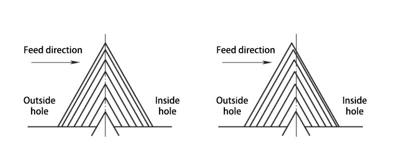
Thread turning adopts the improved reverse lateral feeding method. This method is used to reduce cutting resistance.
It also helps to lower the cutting temperature. In addition, it improves chip removal performance.
There is an axial feed between the two knives. The direction of the axial feed is outward. The axial feed angle is generally set between 1° and 5°.
This allows the chips to be directed outward from the hole. As a result, chip accumulation inside the blind hole is effectively avoided.
The specific method involves turning in 7 feeds. The back draft (ap) values for each feed are as follows: 0.18 mm, 0.17 mm, 0.16 mm, 0.15 mm, 0.14 mm, 0.12 mm, and 0.08 mm.
The axial displacement difference between the two cutting tools for each feed is: 0.005 mm, 0.005 mm, 0.005 mm, 0.005 mm, 0.005 mm, 0.009 mm, and 0.02 mm.
It should be noted that the chip produced by the last feed should be a complete, non-notched V-shaped chip to ensure the integrity of the thread teeth.
Cutting dosage: spindle speed n=800r/min, cooled by water-soluble cutting fluid.
A comparison of thread turning feed methods is shown in Figure 2.
Reference program for CNC thread turning
The thread CNC turning reference program is as follows.
G99;
G99; M04 S800.
T0202.
M08; G00 X18.0 Z25.0; G00 X18.0 Z25.0
g00 x18.0 z25.0.
G92 X20.0 Z-21.093 F2.0; (start thread cutting cycle)
G00 X18.0 Z25.005; (axial displacement 0.005mm)
G92 X20.36 Z-21.088 F2.0; (radial feed 0.36mm)
G00 X18.0 Z25.01; (axial displacement 0.005mm)
G92 X20.7 Z-21.083 F2.0;(radial feed 0.34mm)
G00 X18.0 Z25.015; (axial displacement 0.005mm)
G92 X21.02 Z-21.078 F2.0; (radial feed 0.32mm)
G00 X18.0 Z25.02; (axial displacement 0.005mm)
G92 X21.32 Z-21.073 F2.0;(Radial feed 0.30mm)
G00 X18.0 Z25.025; (axial displacement 0.005mm)
G92 X21.6 Z-21.068 F2.0; (radial feed 0.28mm)
G00 X18.0 Z25.034; (axial displacement 0.009mm)
G92 X21.84 Z-21.059 F2.0;(radial feed 0.24mm)
G00 X18.0 Z25.054; (axial displacement 0.02mm)
G92 X22.0 Z-21.039 F2.0;(radial feed 0.16mm)
g00 x100.0 z100.0.
M09.
M30; (radial feed 0.16mm)
Field test
The process validation test utilizes the CK7163×1500 CNC lathe of Great Wall Machine Tool Works to turn the M22×2-6H blind hole threads of the salvage head.
he pre-processing work of the salvage head has been completed according to the drawings and process requirements.
The diameter of the threaded bottom hole is controlled at φ(20±0.03) mm. The surface roughness of the threaded bottom hole is maintained at Ra ≤ 6.3 μm.
A total of 100 workpieces were selected as test samples. The test was conducted using the aforementioned process and tools.
For thread inspection, an M22 × 2-6H thread plug gauge was used.
Additionally, a metric 60° thread sample plate was employed. Other measuring tools included 0–150 mm vernier calipers and a surface roughness comparison sample block.
The test results are as follows.
(1) The surface roughness value Ra of the test samples are controlled at 1.6~3.2μm.
(2) The test samples are through the gauge through, stop gauge stop, in line with the requirements of the thread gauge test.
(3) The test samples show no light transmission between the threaded side of the tooth and the threaded sample plate.
This indicates a proper fit and no gaps in the contact area.
Additionally, the angle and pitch of the test samples meet the testing requirements of the threaded sample plate.
(4) The small diameter of the thread of the test specimen is controlled at φ(20±0.03)mm.
Therefore, the test samples of M22×2-6H blind hole threads meet the requirements of the drawing.
Conclusion
This paper is based on the process study of the problems in blind hole thread turning.
Improvements were made to the thread turning program. An appropriate threading tool was selected. The cutting parameters were optimized.
These changes enhanced the thread cutting performance and machining stability. Based on these improvements, the following conclusions are drawn.
(1) In the thread turning of M22×2-6H blind holes in the salvage head, an improved reverse lateral feed method was applied.
This method improves the direction of chip flow during machining.
As a result, the problem of poor chip removal performance in the thread turning process is effectively solved.
(2) The problem of low tool life was a significant issue in the thread machining of 3Cr13 material. This problem was solved by applying TiN-coated material inserts.
In addition, integral WC (tungsten carbide) carbide boring bars were used. These improvements effectively extended the tool life during machining.
(3) The optimum cutting dosage for turning M22×2-6H blind hole threads was obtained through field test.

