
Deep and narrow cavity parts are parts with the structural characteristics of large depths, narrow openings or restricted internal space. It is currently one of the problems in the processing and manufacturing.
Typical characteristics of such parts are:
Cavities that are much deeper than they are wide, such as those with depth-to-diameter ratios greater than 3:1, present challenges.
These cavities often have internal structures that are difficult to access or feature limited machining space. Machining such cavities typically requires long, thin tools to cut deep into the cavity.
Characteristics include: deep holes or grooves, narrow openings with long internal spaces, internal structures such as reinforcements, cooling channels, runners, etc…
Due to its deep cavity structure, a tool with a larger aspect ratio must be chosen for machining. This often leads to issues such as vibration and chipping during the processing.
Additionally, there is poor cooling effect and difficulties with chip removal.
These factors contribute to poor machining stability, low cutting efficiency, and short tool life.
Main reasons for machining difficulties include the following.
Poor tool rigidity, easy to vibrate
Deep cavity machining requires the use of long and thin tools. These tools have a large overhang length, which leads to insufficient rigidity.
As a result, vibration and chatter are more likely to occur. This causes poor surface roughness and unstable dimensional accuracy.
Difficulty in chip removal
The narrow cavity space restricts the chip discharge path. This is especially problematic when machining at the bottom of a deep cavity, where chips easily accumulate.
Accumulated chips increase the load on the tool and affect machining stability. They may also scratch the machined surface.
Difficult cooling and heat concentration
When the tool reaches deep inside a narrow cavity, coolant cannot adequately reach the cutting area.
As a result, heat is not effectively removed. This can easily cause thermal deformation and compromise part accuracy. It also leads to increased tool wear.
Poor machining vision, not easy to monitor
The deep and narrow structure makes it difficult for the operator or the machine tool to visualize the machining status.
This limitation increases the risk of errors and hinders effective monitoring of machining quality.
Difficult programming and path design
To avoid interference and collision, tool paths and machining strategies must be carefully designed.
This careful design makes programming complex, especially for 5-axis simultaneous machining.
Complex fixture design
The workpiece has a special structure and is prone to deformation during machining.
Therefore, customized fixtures must be designed for effective support and accurate positioning.
This requirement increases both the preparation time and the overall cost.
Problems in the structure and processing of parts
A deep narrow cavity parts structure and size shown in Figure 1.
Parts material for the 35 steel, forgings, external dimensions of 100mm × 100mm × 220mm, corner R8mm, need to process 49mm × 80mm, 200mm deep through the groove and the side wall of the two sides of the groove.

During the machining process, it is necessary to select a number of tools with a length of 220mm or more for roughing and finishing respectively.
Due to the long tool cantilever, the vibration during machining is large, the tool is prone to chipping, and the depth of cut and feed speed are limited.
With increasing milling depth, the effectiveness of cooling and chip removal at the tool tip gradually diminishes.
As a result, cutting temperatures rise sharply, leading to tool wear, surface hardening, and other adverse phenomena.
These issues cause low cutting efficiency, shortened tool life, and poor surface machining quality. Moreover, the large batch size of this product amplifies these challenges.
Therefore, finding ways to ensure machining quality, improve efficiency, and reduce costs has become an urgent priority.
Machining process optimization
The side wall of the part features two square grooves: one measuring 30 mm × 75 mm and the other 30 mm × 55 mm.
At the bottom of these grooves lies a φ46 mm round hole. Through the deep cavity, there is a 40 mm × 80 mm square groove. Before tempering, φ40 mm through-holes are pre-drilled.
After analyzing the part’s structural characteristics, a priority machining sequence was established.
First, machine the two square grooves in the side wall. Next, pre-drill the Ø46 mm hole to Ø45 mm, retaining the finishing allowance.
This approach ensures that, when the tool reaches the depth of the square-groove and round-hole features, it operates as an “empty-line” tool.
By using an empty-line strategy, the actual cutting volume is reduced.
This reduction not only extends tool life but also increases cutting speed.
In addition, first machining a sidewall hole slot helps facilitate chip removal. This prevents chips from accumulating and causing issues such as tool chipping and workpiece surface hardening.
Selection of milling method
The inner cavity of the part is 200 mm deep, requiring the removal of a large volume of hard material.
To ensure efficient machining under these conditions, selecting the appropriate milling method is especially important.
After analysis, two machining solutions can be excluded. The workpiece is a tempered part with high hardness and a deep cavity.
Therefore, pendulum milling and dynamic milling are not suitable.

Insertion milling method (see Figure 2) offers distinct advantages for deep cavity machining.
It is one of the most effective ways to achieve a high material removal rate in metal processing.
The principle involves replacing the traditional horizontal feed with axial insertion, converting radial cutting forces into axial ones.
As a result, even with a large tool overhang, the tool holder maintains high rigidity, reduces machining vibration, and enhances cutting stability.
During insert milling tests, it was found that a larger cutting width leads to high material removal efficiency.
However, this also generates significant processing vibration, making the tool prone to chipping.
If the cutting width is reduced, the processing efficiency is low, and the tool wear is faster.
If the ordinary alloy milling cutter for insert milling processing, the low life of the insert, the processing effect is poor, and thus need to use a special insert milling cutter blade.
Due to the large cutting volume of this workpiece, this cutting method is excluded when the preparation conditions are limited.
However, efficient machining of deep cavity parts can be achieved using the insert milling method under the right conditions. These conditions include:
A rigid, well-designed part structure and suitable material.
Sufficient preparation before machining.
A special insert milling cutter with high tool life.
Under general processing conditions and without a specialized insert milling cutter, the cavity’s structural characteristics must guide the method choice.
Considering these characteristics, it is more suitable to use the conventional layered milling method for processing.
The workpiece should be pre-drilled φ40mm holes before tempering, as a milling cutter machining down point.
According to cutting experience, tempered steel parts benefit from a specialized machining program for deep cavities.
This program uses a small depth of cut, high spindle speed, and large feed rate. It delivers both high process stability and excellent processing efficiency.
Corner pretreatment
Due to the deep, narrow cavity at the inner corner, the contact area between the tool and workpiece increases suddenly.
This causes a sharp rise in cutting force and makes the tool prone to breakage or collapse. Therefore, the cavity’s inner corner should be pre-treated.
For pre-drilling treatment, use an extended drill whose diameter is slightly larger than the corner radius.
Leave a small margin when drilling to reduce the cutting force at the corner. This approach also helps minimize cutting vibration.
Tool selection
(1) Selection of tool material
According to the characteristics of deep cavity milling processing, the tool must have superb wear resistance.
It also needs excellent heat resistance. At the same time, the tool should possess sufficient bending strength and toughness to withstand the demanding conditions.
Among the commonly used cemented carbide cutting tool materials, the YG type offers superior bending strength and impact toughness.
This makes it particularly well-suited for cutting brittle metals.
The YT type of cemented carbide has higher strength, wear resistance, and heat resistance compared to the YG type.
However, the bending strength of YT type is lower, particularly its impact toughness. As a result, the YT type is more prone to chipping.
YW type cemented carbide offers high toughness, high hardness, and high wear resistance.
It combines the performance characteristics of both YG and YT types of cemented carbide. As a result, YW type cemented carbide has excellent overall performance.
The selection of YW type cemented carbide can effectively improve the processing efficiency and processing quality.
(2) Selection of tool structure
In deep cavity milling, several factors need to be considered. These include the number of teeth on the tool and the length of the depth of suspension.
Additionally, the rigidity of the tool, the chip space, and vibration must be taken into account.
It is also important to address potential tool wear and related issues that may arise during the machining process.
Based on these factors, a large-feed end mill (see Figure 3) should be used for rough milling to ensure strength and cutting efficiency;
The indexable right-angle end mill (see Figure 4) is used for finish milling the cavity and clearing the corner.


Optimization of machining methods
In deep cavity parts machining, tool rigidity plays a crucial role. It is directly proportional to the cutting amount.
By increasing tool rigidity, both machining accuracy and machining efficiency can be significantly improved.
(1) Rough milling is divided into two steps, the first selection of φ32mm conventional large feed end mill, tool overhang 115mm, machining to a depth of 110mm;
Then use the same diameter specifications to increase the large feed end mill, overhang 205mm, machining to 110 ~ 200mm, vibration and wear significantly improved.
(2) In the deep cavity machining process, roughing is carried out in two stages.
First, a conventional large-feed end milling cutter is used. Then, an extended feed end milling cutter is applied to continue the roughing process.
After roughing, an indexable right-angle end milling cutter is used for finish milling. This tool is also used to clear the rounded corners of the cavity.
Considering potential issues such as installation, manufacturing, and processing errors of the two cutters used in rough milling, interference may occur.
Specifically, these errors can lead to interference between the large-feed end mill shank and the machined slot wall in the 0–110 mm range.
To avoid this, the machining size relative to the first cutter is intentionally reduced by 0.1–0.2 mm.
This reduction prevents possible interference. Afterward, layered finishing is performed using an indexable right-angle end milling cutter.
3) Optimization of machining tool path.
The use of pre-drilled holes as tool path entry points helps guide the tool smoothly into the material.
By using an arc-tangent entry and exit method, the tool can enter and leave the part in a smooth and controlled manner.
This ensures that the cutting force does not change suddenly.
During the cutting process, the principle of “thick-in, thin-out” is applied.
This means the chip is thicker when the tool enters the workpiece and thinner when it exits. This method, known as smooth milling, effectively reduces tool vibration.
As a result, it helps improve tool life and enhances the surface quality of the groove walls.
The optimized machining tool path is shown in Figure 5.

Optimization of cutting parameters
Cutting speed, depth of cut and feed rate are the main factors affecting cutting efficiency.
According to machining experience, cutting speed has the greatest impact on tool life.
If the cutting speed is too small, it affects the machining efficiency;
If the cutting speed is too large, it affects tool life. Feed speed on the tool life of the second influence, the depth of cut on the tool life of the smallest impact.
According to processing experience, debugging parameters can be roughly classified into two types.
The first type involves a large depth of cut combined with a small feed rate.
The second type uses a small depth of cut along with a large feed rate.
According to the range of cutting parameters provided by the tool manufacturer for debugging cutting.
YW carbide milling 45 steel tempered parts, cutting speed of 150-300m/min, feed 0.15-0.3mm/r, depth of cut 0.3-1.2mm.
Since the cutting speed has the greatest impact on tool life, the cutting speed was micro-adjusted to debug the depth of cut and feed rate.
The debugging results of the cutting parameters of the large feed tool are shown in Table 1.

According to the results in Table 1, for this tool material and part material, “small depth of cut, large feed speed” cutting method of higher processing efficiency, longer tool life.
The test cutting results are:
Large feed cutting speed of 181m/min, feed rate of 2500mm/min, depth of cut of 0.8mm, at this time the cutting vibration is significantly reduced, the wear tends to be normal.
When the use of a larger and larger feed tool, it is necessary to reduce the feed rate to 80% of the normal tool.
Cooling technology
Another key point to improve efficiency in metal cutting is cooling.
Cutting heat affects the formation and discharge of chips, such as cooling in the traditional way, the heat dissipation effect is poor, will intensify tool wear and shorten tool life.
High-pressure cooling cutting technology involves increasing the pressure of the cutting fluid to a specific level.
The fluid is then precisely sprayed onto the required cooling area to achieve rapid cooling.
One key feature of this method is that the high-pressure cutting fluid instantly removes chips from the cutting zone.
This results in smoother part processing and faster cooling, which in turn helps extend the life of the tool.
Compared with the ordinary cooling method, it can enhance the tool feed speed and depth of cut to a small extent, and improve the machining efficiency.
In this cutting process, the combination of high-pressure internal cooling and external cooling is the best cooling effect.
The machining center without internal cooling is selected for this machining, and the combination of cutting fluid and high-pressure air-cooling is adopted.
The high-flow cutting fluid tube is aligned with the tip of the tool during machining to reduce the temperature and play the role of cooling and lubrication.
The air-cooled tube is aimed at the front of the tool, which can quickly blow away the chips and ensure smooth tool processing.
Research results
By comparing the data before and after the test, it was found that process improvements have a noticeable impact.
Specifically, adjusting the machining parameters and optimizing the process can effectively enhance the efficiency of deep cavity machining.
In the test, different cutting speeds, feed speeds, and cutting depths were selected, while keeping all other parameters unchanged.
The results showed that the highest machining efficiency was achieved under specific conditions.
This occurred when using a large feed tool for roughing, with a cutting speed of 181 m/min, a feed speed of 2500 mm/min, and a cutting depth of 0.8 mm.
The process is optimized through reasonable arrangement of work processes, selection of high-efficiency tools and adoption of cooling technology.
By comparing the data before and after the test, it was found that the optimized machining method offers significant improvements.
It shortens the machining time by 45%, increases tool life by 30%, and reduces downtime by 15%.
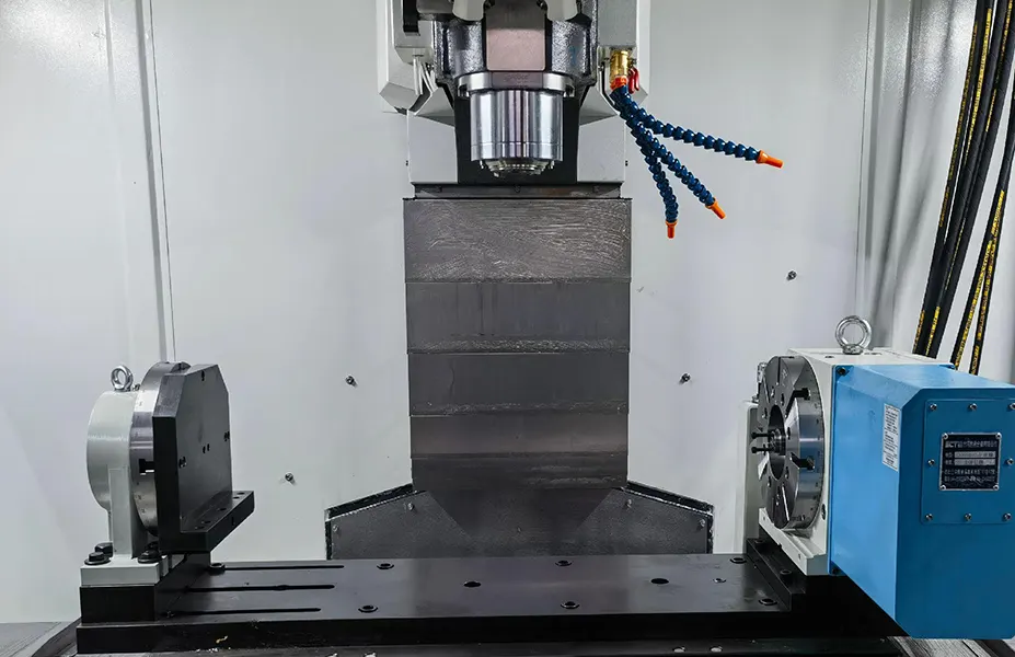
Overall, it achieves the same machining effect as using professional tools and equipment for deep-cavity parts (see Figure 6).
Figure 6 Machining effect
Conclusion
This paper takes a deep narrow cavity part as an example to develop a new milling processing method, which solves the problems of vibration, chip removal difficulties and chipping in the machining process.
The results of the study show that there is no universally best machining method in metal processing.
Instead, the most suitable method depends on the specific situation of the machining process and the requirements at hand.
By optimizing the process, selecting appropriate tools and machining parameters, and applying effective cooling and other measures, it is possible to significantly improve efficiency.
Even ordinary tools can be used effectively to enhance CNC deep cavity machining performance.
At the same time, in actual production, also need to consider the impact of other factors such as workpiece clamping, equipment rigidity.

