
In control and propulsion products, many parts and components require deep small hole processing. This is especially true for propulsion products that use difficult-to-machine materials.
During deep small hole machining, issues such as drill breakage, drilling deviation, and elliptical holes occur frequently.
These problems lead to a low qualification rate in processing. As a result, deep small hole machining has become a major technical challenge in the production process.
The traditional clamp machining process method is low-productivity, which seriously restricts the product’s production capacity.
In the two-component thruster, oxygen and the combustion propellant flow into the chamber in a specific proportion.
They are then mixed uniformly to achieve effective atomization and efficient mixed combustion.
This provides the force and torque required for orbital and attitude control during the period of in-orbit.
The deep, small holes on the thruster board suffer from poor size and shape tolerance. This seriously affects the flow of propellant and the thruster’s overall performance.
At the same time, the thruster board’s qualification rate remains low, which has significantly impacted normal scientific research and production activities.
As a result, human resources, material resources, and equipment have been seriously wasted.
Improving the machining process is urgently needed to meet the product’s design and manufacturing requirements.
Improvements in processing technology are urgently needed to meet the requirements of product design and processing and to improve the product qualification rate.
Thruster board introduction
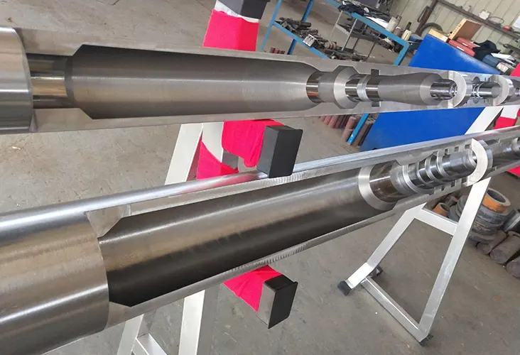
The thruster board (φ56 mm graphic on the front side of the workpiece) is a key thruster component.
It primarily functions in oxygen ventilation and combustion within the porous structure. The thruster board is made of Ti53311S.
There are two deep holes on the side of the long plugs (as shown in Fig. 1):
One with a diameter of φ0.8 mm and a depth of 24.5 mm,
The other with a diameter of φ1.0 mm and a depth of 30.5 mm.
These holes result in a maximum depth-to-diameter ratio of 21. Blind holes — 2-φ(7+0.02/0) mm and 2-φ3(+0.02/0) mm — must intersect with the deep holes such that half of the deep holes are exposed.
At the same time, these intersecting features must be precisely aligned to ensure the safety of the thrusters.
The maximum depth-to-diameter ratio is 21. Two blind holes — 2-φ(7+0.02/0) mm and 2-φ3(+0.02/0) mm — must intersect with the deep holes so that half of the deep holes are exposed.
At the same time, the straightness of the internal deep holes must be very high to ensure the thrusters’ required flow rate.

Processing difficulties
Due to the thruster board processing material Ti53311S, and deep small hole depth ratio is large, the processing process has the following difficulties:
( 1) The material Ti53311S is difficult to process due to its high Vickers hardness (HV0.2 about 350). The internal microstructure is generally isometric α-organization (Figure 2a).
However, it can also contain mixed organizations, such as net basket organization (Figure 2b).
This means the organization is not uniformly distributed, leading to the formation of hard points.
These hard points can cause deviations in hole drilling.
( 2) When using a manual drilling machine to process deep and small holes with a large depth-to-diameter ratio (φ0.8 mm and φ1.0 mm), the drill bit has low strength and high rotational speed.
This high rotational speed generates a large amount of heat during the process.
Moreover, the drill bit’s spiral groove is narrower, hindering smooth chip removal.
The coolant is also difficult to supply through the spiral groove, preventing effective heat dispersion.
As a result, problems such as drill bit fracture, drilling deviation, and drilling ellipse are more likely to occur.
These issues lead to a low qualified rate of machining.

( 3) It is not possible to observe the internal state in time during blind hole machining.
( 4) Up to 300 thruster boards are produced each year, and manual processing increases the operator’s labor intensity.
The productivity is also low, and the consistency of the product is poor.
Improvement measures
To address the issues of hole deviation, impermeability, and drill bit breakage caused by processing deep and small holes in the thruster board, we conducted research.
Our focus was on deep and small hole processing technology.
We found that these problems can be solved by using a CNC EDM high-speed piercing machine to create guide holes and then reaming the holes with reaming drills.
This approach improves both product quality and processing efficiency.
Specifically, through the following four aspects of improvement: First, EDM pilot hole drilling.
Firstly, the design of the EDM pilot hole drilling tire.
The second is the choice of parameters for EDM pilot hole drilling.
Third, the clampsman to produce an easy-to-mount positioning of the reaming tire; Fourth, the selection of reasonable cutting parameters.
The fourth is to choose reasonable cutting parameters, and use the reaming drill to ream holes to φ1 mm, φ0.8 mm.
The following are specific improvement measures.

The choice of EDM pilot hole parameters
The size of the pilot hole and the surface quality during EDM machining play a crucial role in the difficulty of clamp reaming.
Determination of Electrical Machining Parameters
The electrical machining parameters are identified through process testing.
A metallurgical microscope is then used to observe the microscopic morphology of the processed holes.
The parameters resulting in smaller fusion tumors and higher surface quality are the most reasonable.


Selection of Brass Electrode Diameter
The diameter of the brass electrode must be carefully chosen to ensure the accuracy of clamp reaming and to allow for convenient operation.
This is particularly important when processing φ1 mm and φ0.8 mm deep small holes.
In testing:
φ0.8 mm and φ0.7 mm brass electrodes were used for φ1 mm pilot holes.
φ0.6 mm and φ0.5 mm brass electrodes were used for φ0.8 mm pilot holes.
The clamp operator then reamed the holes using φ1 mm and φ0.8 mm drills.
Comparison of Reaming Difficulty
The pilot holes processed with:
φ0.8 mm brass electrodes were easier to ream than those punched with φ0.7 mm.
φ0.6 mm brass electrodes were easier to ream than those processed with φ0.5 mm.
However, as shown in Table 2, the smaller pilot holes also increase the risk of drill bit folding.
Analysis of Reaming Difficulty and Drill Failure
As shown in Figure 5:
When the drill reaches the pilot hole, it repairs the inner wall of the hole (Fig. 5a).
The harder recast layer requires more material removal if the pilot hole is too small.
Combined with the reduced drill strength, this increases the likelihood of breakage (Fig. 5b).
Electrode Consumption and Depth Calibration
During EDM drilling, the brass tube electrode is continuously consumed.
As a result, the electrode’s shortening is not equal to the hole depth in the thruster board.
To ensure accuracy, it is necessary to determine the electrode shortening using a test piece.
Through testing:
The brass tube must move down 48 mm for a φ0.8 mm pilot hole with a final depth of 24.5 mm.
The brass tube must move down 58 mm to accommodate a φ1 mm pilot hole with a depth of 30.5 mm.
Design of the clamp reaming tire tool
A specialized clamping reaming fixture is required to ensure the dimensional and positional accuracy of deep small hole machining.
This fixture must meet the following design requirements:
( 1) The positioning pin hole of the fixture is consistent with the positioning hole of the pilot hole made by wire-cutting.
( 2) Special measures are taken in the fixture design to prevent the flatness of the processed thruster board from affecting the distance between the micro-hole and the end face.
At the fixture’s center, a grooved hole with a diameter of φ56 mm and a depth of 2 mm is machined.
( 3) Since the φ0.8 mm and φ1 mm holes must be machined from both ends by turning the workpiece over, they must be aligned precisely head to head.
This ensures that the two small holes processed from each end lie on the same straight line.
To achieve this, the parallelism of the upper and lower end surfaces must be controlled within 0.02 mm.
( 4) U-shaped openings need to be made on the workpiece’s upper and lower surfaces at the tire’s drilling position.
This design helps reduce the reaming drill’s overhang length and prevents interference between the drill chuck and the tire during the drilling process.
The clamping reaming tire and its mounting diagram is shown in Figure 6.

Selection of Cutting Parameters for Jaw Reaming
Choosing the appropriate speed and feed is necessary to ensure reaming accuracy and less wear on the drill.
Through process testing, it was found that drill bit wear becomes more severe when the machine runs at 5,000 r/min.
As a result, the drill bit needs to be sharpened frequently. Additionally, the feeding process becomes more difficult and labor-intensive.
In severe cases, the drill bit may even break. At the same time, the precision of the deep hole dimensions is also negatively affected.
When the rotational speed is 4000 r/min, the drill bit’s torque is greater, and the working efficiency is lower.
In the end, proper machining parameters must be selected to ensure the efficiency, accuracy, and straightness of small holes.
The recommended rotational speed is 4,500 r/min, and the appropriate feed speed ranges from 3 to 4 mm/min.
Conclusion
Hole machining accuracy is greatly improved by using a high-speed piercing machine to create guide holes and applying the clamping reaming method for deep small hole processing.
As a result, the average pass rate increased from about 70% to over 98%, and processing productivity rose to more than three times the original level.
At the same time, production costs were significantly reduced.
This processing method can be applied in the subsequent machining of the thruster board for large-thrust engines.
It can also serve as a process reference for machining deep and small holes in new research products that have a larger depth-to-diameter ratio.

